SOLIDWORKS Simulation Connectors: A Primer
SOLIDWORKS Simulation Connectors may be used to simplify behavior without actually including a physical part such as a bolt or pin. This is a primer on the different types of connectors available in SOLIDWORKS Simulation.
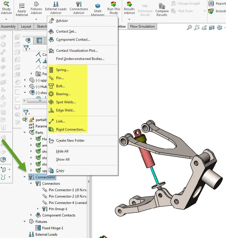
Types of Connectors
Ridge
A Rigid connector ![]() rigidly connects faces from one solid body to faces from another solid body. The faces can only deform rigidly as a group. The distance between any two locations on the faces remains constant.
rigidly connects faces from one solid body to faces from another solid body. The faces can only deform rigidly as a group. The distance between any two locations on the faces remains constant.
Springs
There are 3 types of Springs:
- Compression Extension Spring: These are general purpose springs that generate forces as soon as parts connecting them start to move.
- Compression Spring: You can use them to model rubber bumpers or springs that provide a compressive interface when sandwiched between two parts.
- Tension Spring: You can use them to model cables or ropes that cannot take compressive loads but can significantly affect the overall stiffness under tension.

Pin
An assembly consists of multiple parts connected to each other with pins, bolts, screws, or springs. Examples of assemblies with pins include laptops, scissors lifts, pliers, and actuators. To model the behavior of such assemblies, traditionally, you have to create each pin geometry and apply contact conditions between the pins and their contacting faces, a computationally expensive approach.
Elastic Support
An Elastic Support ![]() defines an elastic foundation between the selected faces of a part or assembly and the ground. This connector resists tension and compression.
defines an elastic foundation between the selected faces of a part or assembly and the ground. This connector resists tension and compression.
Bolt
A Bolt ![]() can connect two components, multiple components, or a component and the ground. You can define bolts through a mixed stack of solids, shells and sheet metal bodies. You can also define a bolt by selecting entities of the same component.
can connect two components, multiple components, or a component and the ground. You can define bolts through a mixed stack of solids, shells and sheet metal bodies. You can also define a bolt by selecting entities of the same component.
Simulation models a bolt connector in a spider-like arrangement with (a) a beam element to represent the bolt shank, and (b) rigid bar elements to represent the nut and head parts.
Link
A Link ![]() ties any two vertices or reference points on the model by a rigid bar that is hinged at both ends. The distance between the two locations remains unchanged during deformation.
ties any two vertices or reference points on the model by a rigid bar that is hinged at both ends. The distance between the two locations remains unchanged during deformation.
Edge Weld
Available in SOLIDWORKS Simulation Professional and SOLIDWORKS Simulation Premium.
Spot Weld
A Spot Weld ![]() connects two or more thin overlapping metal sheets at small areas (spots) without using any filling material.
connects two or more thin overlapping metal sheets at small areas (spots) without using any filling material.
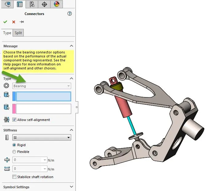
Bearing
You define a bearing connector between split cylindrical faces of a shaft and cylindrical or spherical faces of a housing. You can use a bearing connector when the housing is not much stiffer than the shaft.
Expand Your SOLIDWORKS Simulation Skillset
Troubleshooting SOLIDWORKS Simulation No Penetration Contact Sets Recommendations
Piecewise Nonuniform Pressure in SOLIDWORKS Simulation
Changing Units and Number Formats in SOLIDWORKS Simulation
SOLIDWORKS Simulation Tips: No Penetration Contact Set Setup
A Guide for Using Bearing Connectors in SOLIDWORKS Simulation
Get our wide array of technical resources delivered right to your inbox.
Unsubscribe at any time.