SOLIDWORKS Simulation Global Contact Option Explained
SOLIDWORKS Simulation users often call into our tech support line needing advice as to why their model is not stable. In many cases, they have deleted their Global Contact condition or changed it from its default setting of bonded to no penetration. Most of the time this is not necessary.
There are three contact options in the Component Contact command window. (Figure 1)
- No Penetration: This option allows two or more faces to touch and develop contact pressures/forces, as well as move away from each other. What it does not allow is to let the two faces flow into each other and take up the same space together. (Suggested Article >> SOLIDWORKS Simulation Tips: No Penetration Contact Set Setup)
- Bonded: This allows two touching faces or faces with a specific gap between them (when specified by using the Non-touching faces option) to remain touching or to force the gap to remain the same size no matter what loads are placed upon the two faces during the analysis. As far as Simulation is concerned, when two parts with two faces are bonded they are actually one part.
- Allow Penetration: This contact feature allows multiple parts to flow into each other during the analysis at the specified faces while the analysis is being run. This contact option is mostly used in frequency and buckling analysis.
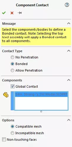
Figure 1: Component Contact CommandManager
It is a rare situation where the No Penetration contact set should be used for a Global Contact set. The reasons for this are because SOLIDWORKS Simulation must constantly check all the No Penetration contact sets in a study to see if they are still meeting the No Penetration criteria.
Because of this, No Penetration contact sets are very computationally intensive and can take a considerable amount of time and computer resources to solve accurately during a simulation analysis. This is especially true for large assemblies.
No Penetration contact sets do not keep parts together they allow the parts to move apart without resistance. This is why the Global No Penetration contact set could become unstable during the analysis where parts just fly off into space.
All Global Component Contacts default to Bonded which I recommend you leave on because any component contact and local contact set automatically overrides the Global Component Contact set so you do not need to worry about them negating each other. A good way to think about it is that local contacts always trump Global Contacts.
To get to the CommandManager that allows a local contact set to be created first right-click on Connections. At the top of the pop-up menu that appears after this action, click on Contact Set to open the Contact Sets CommandManager. (See figure 2)
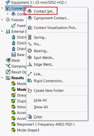
Figure 2: Click here to open up the Contact Sets CommandManager
After opening the Contact Sets CommandManger, the Simulation user can specify what type of local contact he/she would like to utilize and then choose the faces that the contact set will be applied to.
The reason why local contact sets are useful is that the Global Contact and component contact set does not always “grab” and apply the right or even any contact between two or more faces that need to have contact sets for the Simulation to be stable.
For example, if an edge or point of one part is meant to be bonded to a face of another part the Global Contact set would not apply a contact condition to these parts. The user needs to recognize where these types of contacts are and apply them manually in a local contact set.
Computers are not smart enough to recognize every situation and apply the correct contact sets perfectly every time. Simulation users making engineering decisions are always necessary to correctly set up a new simulation. The SOLIDWORKS Simulation Global and Component contact command windows may make the job easier, but it is always necessary for the engineer to review all contacts and adjust manually as necessary.
More SOLIDWORKS Simulation Tutorials
What's New SOLIDWORKS 2022: Simulation, Flow, & Plastics
Free SOLIDWORKS Simulation Tutorials
SOLIDWORKS Motion Analysis Motor Torque & Power
SOLIDWORKS Simulation Gauss Points, Nodal, and Element Stress
Troubleshooting SOLIDWORKS Simulation No Penetration Contact Sets Recommendations

About Taran Packer
Taran is a SOLIDWORKS Simulation Technical Support Specialist at GoEngineer. He has a Bachelor’s degree in Biomedical Engineering from the University of Utah. Taran enjoys learning about different tools in SOLIDWORKS Simulation, Flow Simulation, and Plastics.
Get our wide array of technical resources delivered right to your inbox.
Unsubscribe at any time.