SOLIDWORKS Simulation Using Specific Displacement in Design
Designers are often given scenarios where there is a displacement limit in a design but they need to either find the amount of force that will be required to reach that displacement, or, the displacement limit and force is known, but the design needs to be optimized to work within the given requirements. SOLIDWORKS Simulation is an excellent tool for a situation such as this.
In this exercise, we will start with a simple part that will be given a specific displacement. The part will have two configurations, one flat and one with a rib to increase rigidity and we will show how this method can be used to help in designing a part with the necessary rigidity for the application.
Model Geometry
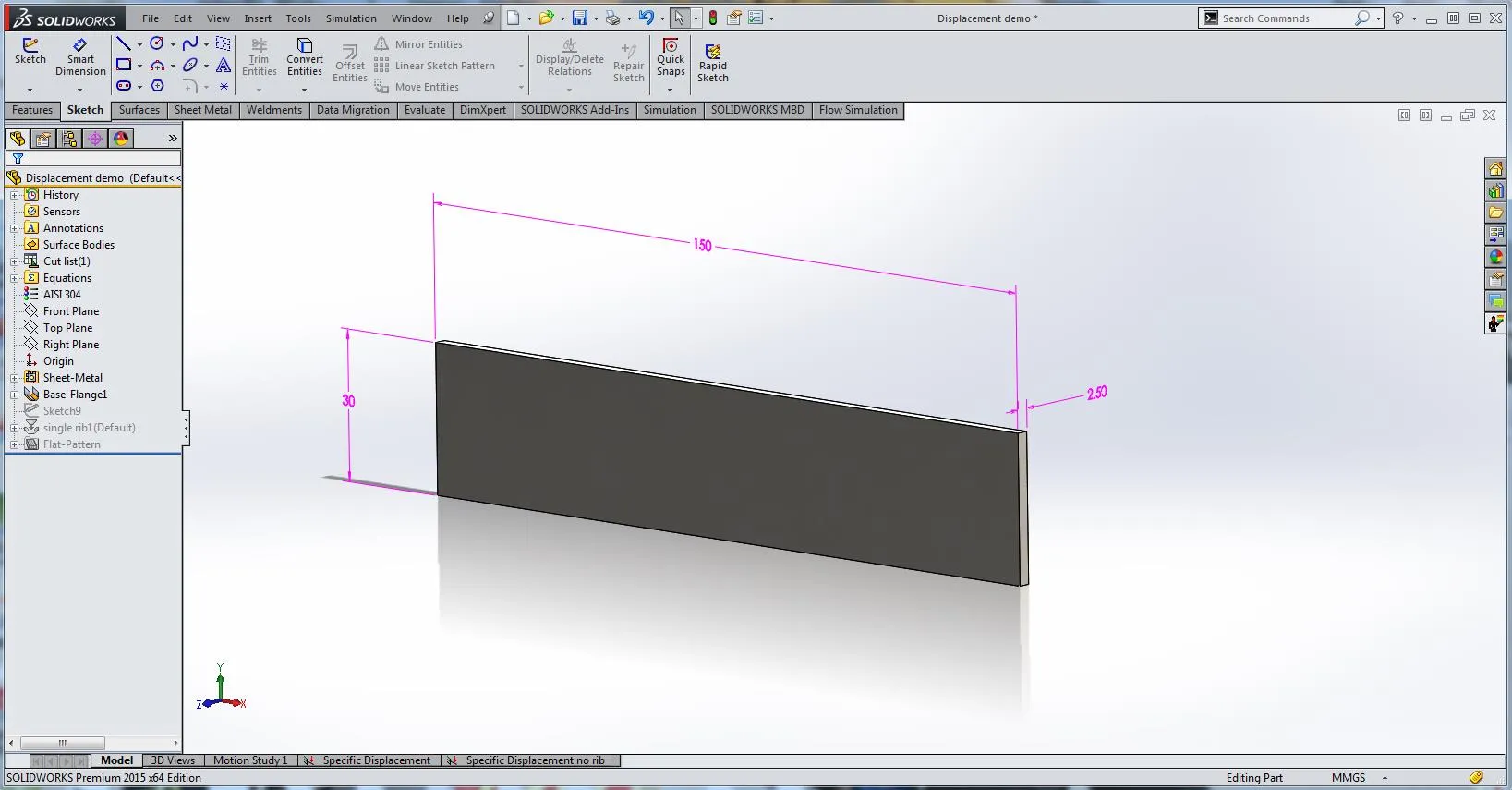
Here is the overall geometry of the part that will be used in this exercise.
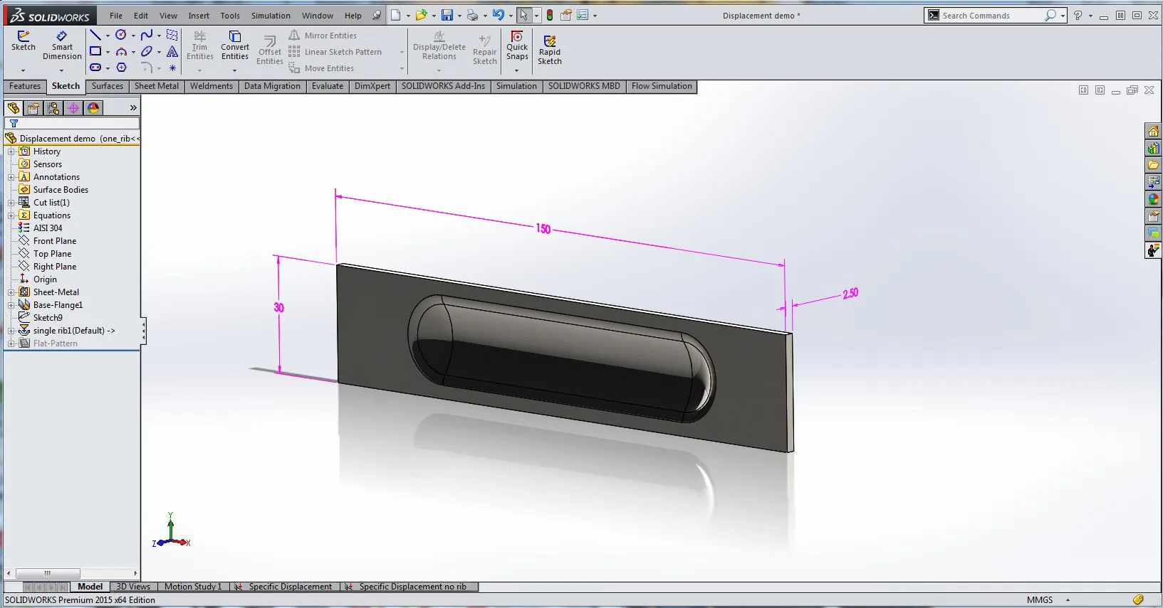
Here we see the second configuration that will be used. To create this, the standard Rib forming tool was used and positioned at the center of the sheet metal.
Study Setup
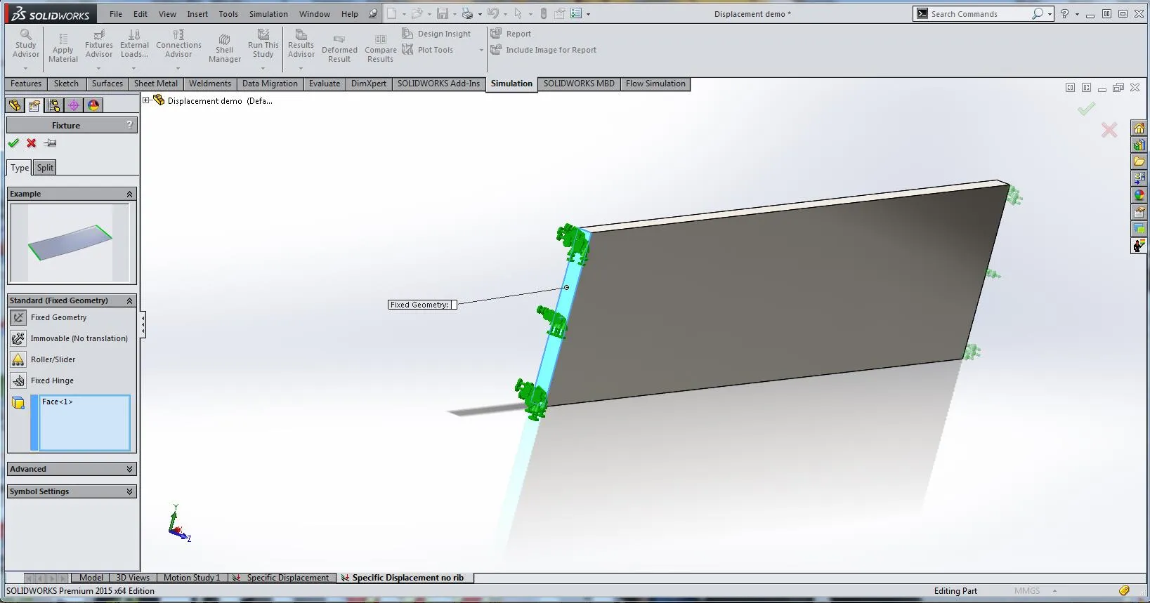
In SOLIDWORKS Simulation, we create a static study. In Fixture, we set one end (face) of the part to have Fixed Geometry.
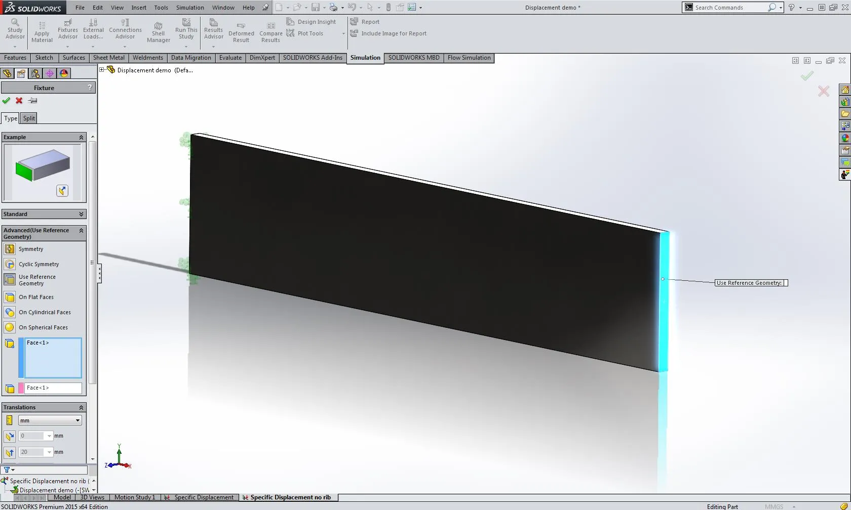
Next, we again use Fixture, go into Advanced and set the opposite face of the part to use reference geometry. With this, we can set a specified translation in any direction we choose. In this exercise, we will set a translation in the Z-direction of 20mm.
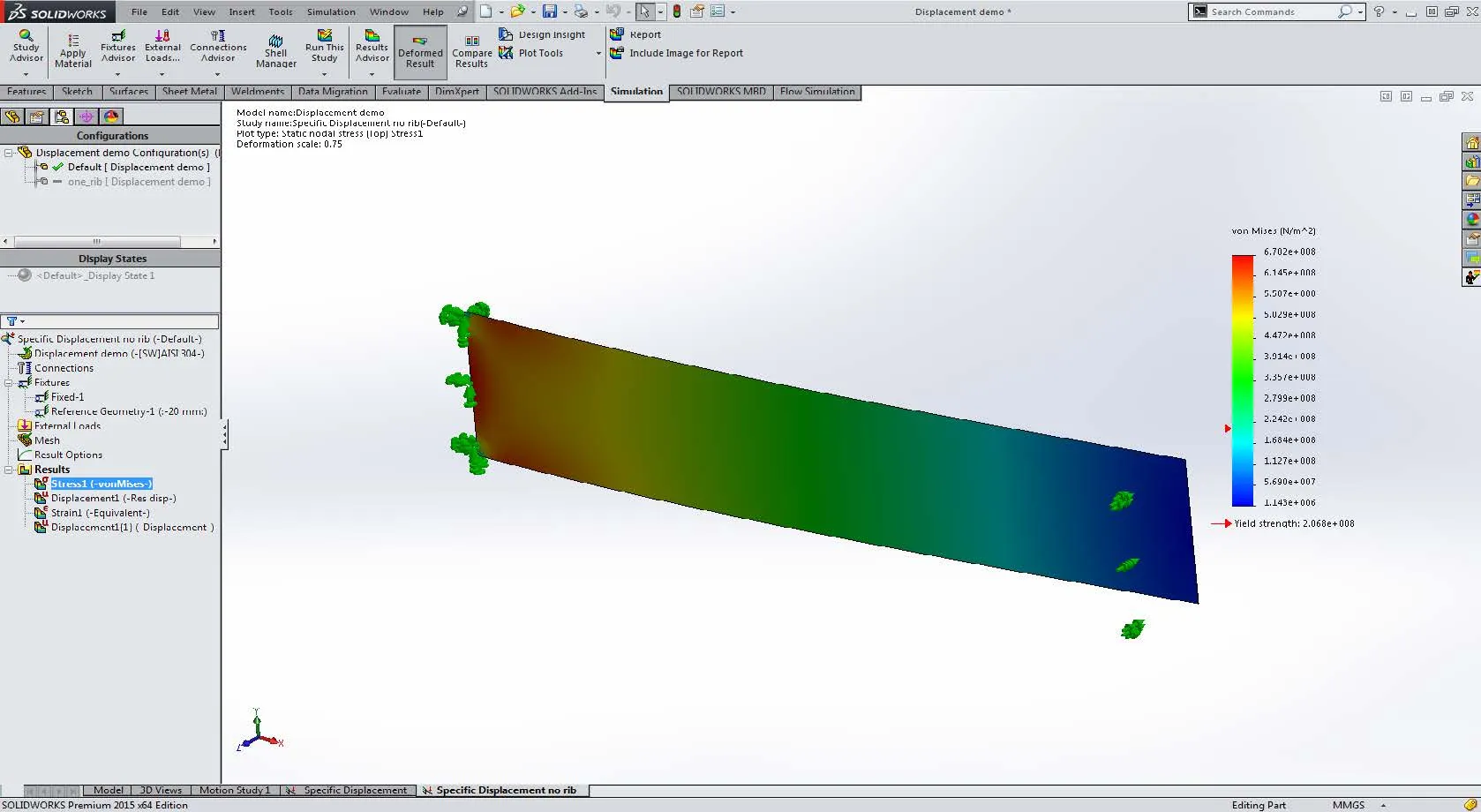
Once this is finished create a mesh and run the simulation. The results should look something like this.
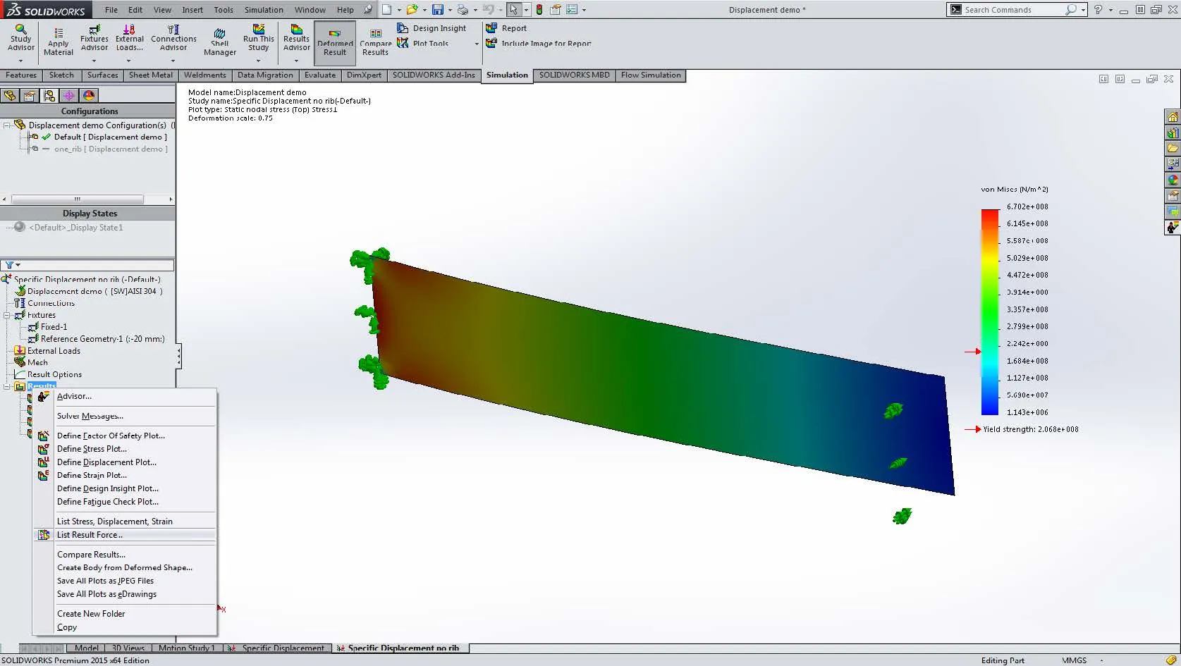
Now that the part is fixed and has a set displacement we can look at the reaction forces required to achieve this displacement. To do this Right-click on Results, scroll down, and select List Result Force…
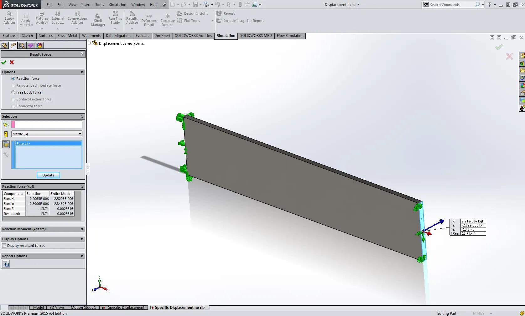
Here, we select the face that was translated, select Metric results, and we see that the flat sheet required 13.7kgf to be displaced 20mm.
To compare this to the design with the rib, we right-click on the study and select Duplicate study, and select the Rib configuration. This will copy the study setup onto the other configuration.
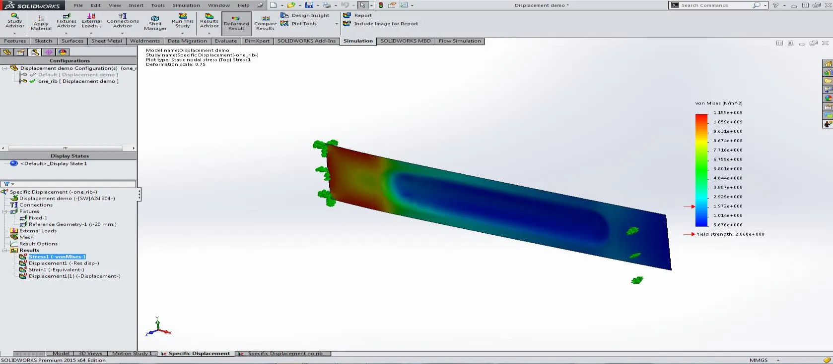
Again we follow the same steps to find the reaction force.
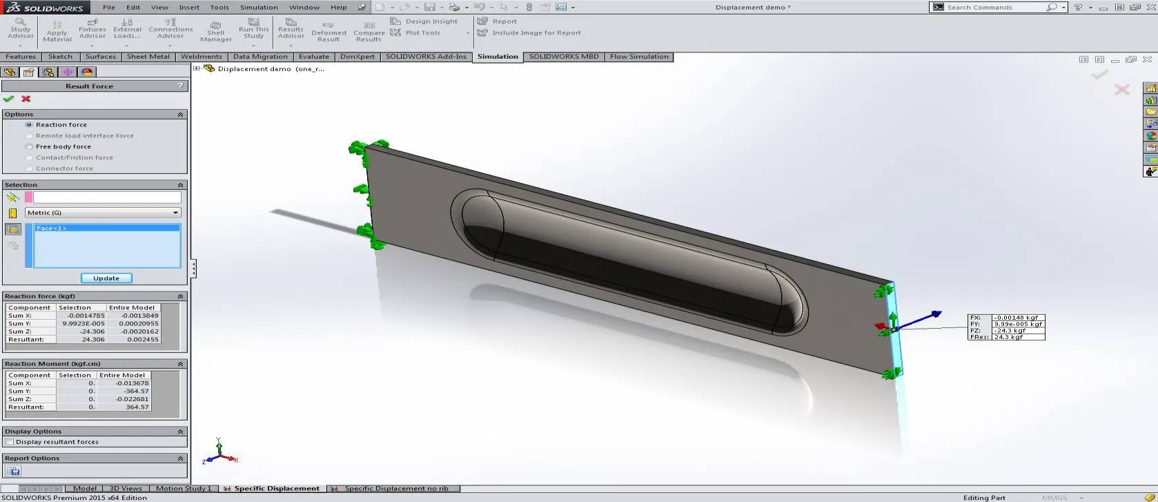
We see that with the rib the force required for 20mm of displacement is 24.3kgf, considerably higher than without the rib. This is a very powerful technique that can be used to optimize a very wide range of designs.
Learn More About SOLIDWORKS Simulation
What Determines the Default Mesh Size in SOLIDWORKS Simulation?
Prescribed Displacement to find Reaction Force in SOLIDWORKS Simulation
Introduction to Validation Equations in SOLIDWORKS Simulation
SOLIDWORKS Simulation Energy Norm Error Plot

About Brian Childree
Originally from Montana, Brian served in the US Air Force where he did machining and welding on A-10s and F-16s while stationed in Alaska and Afghanistan. He’s worked as a Design Engineer in multiple industries from medical, oil and gas, aerospace, consumer products and even interior lighting design. He graduated from the University of Utah’s Mechanical Engineering program and now works at GoEngineer as an Applications Engineer specializing in Simulation analysis.
Get our wide array of technical resources delivered right to your inbox.
Unsubscribe at any time.