Stratasys Catalyst Software - Generating Multiple Contours
Stratasys 3D printers are some of the best on the market. They are reliable and repeatable and, part of that is due to the software that comes with the printer.
There are different levels of software that come with the FDM 3D printers.
The Mojo Print Driver behaves like your typical printer software. Catalyst software for the design series printers is a little more robust but not as robust as the Insight software. With Insight software, the operator is able to customize every facet of the printing of their part. They can modify the geometry of the part on a layer-to-layer basis. Or insert pauses into the build to change material or imbed an object and print over it. They can also increase the number of contour layers with the simple click of a button and so much more.
The most effective way of adding strength to a part is to increase the number of contour layers after optimum orientation has been selected. It is also useful when you want to “add meat” to a boss or hole for tapping or cutting functional threads. What does it mean to add contour layers?
Picture concentric circles fused together. But what happens when you need the increased contours strength but you don’t have insight? I have come up with a way to trick insight into applying contours to depth by adding concentric walls in my SOLIDWORKS part. This process can add increased contours functionality to the most rudimentary FDM software.
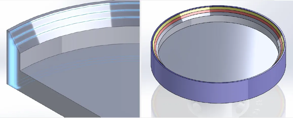
As you can see above, the part has concentric “shells” or parts that are separated by a minimum of 0.002” gap. When this file is loaded into Catalyst, the software sees those gaps and applies contour lines around them. With some quick calculation you can make each “shell” the thickness of two contour lines. Thereby multiplying the default single contour by the amount of “shells” you separate from your original part.
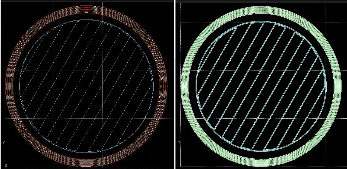
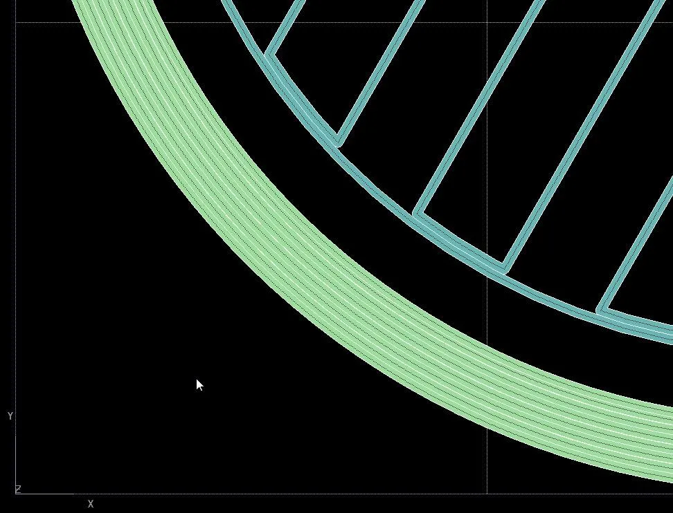
The concentric “shells” are shown on the right with toolpaths contouring to them. On the right the toolpaths have been shaded and below you can see that the part is more monolithic. There are fewer air gaps between the paths of material. Therefore the part will be stronger.
If you have any questions about how this worked or just want to see a demonstration of how the printers work feel free to contact us!
More 3D Printing News
Meet the Stratasys H350 3D Printer
Stratasys J35 Pro Material Configurations
Painting Clear PolyJet Parts: 3D Printing Hacks
Stratasys VeroUltra White and Black Materials for Color 3D Printing
![]()
About GoEngineer
GoEngineer delivers software, technology, and expertise that enable companies to unlock design innovation and deliver better products faster. With more than 40 years of experience and tens of thousands of customers in high tech, medical, machine design, energy and other industries, GoEngineer provides best-in-class design solutions from SOLIDWORKS CAD, Stratasys 3D printing, Creaform & Artec 3D scanning, CAMWorks, PLM, and more
Get our wide array of technical resources delivered right to your inbox.
Unsubscribe at any time.