STRATASYS – Reducing the Cost of FDM 3D printing
The Classic Consumables Business Model
The ‘razor and blades’, the ‘camera and film’, the ‘printer and ink’……It’s a proven business model where the consumables associated with a particular product are responsible for most or all of the profits. It’s also a model that has made its way into the 3D printing world. By the time large 3D printing equipment manufacturers develop the technology, design, engineer, test, manufacture, market, sell, and support the equipment, there probably isn’t much margin in the system itself.
It would seem reasonable to me that the hardware/printer sales merely cover the overhead but more importantly act as a vehicle to carry the materials and other consumables business that drives most of the profits.
As frustrating as the business model is to the heavy consumer — there are ways we can buck the model to reduce material costs and allow 3D printed parts, tools, jigs, and fixtures to be used where the material volumes and associated costs would otherwise make them cost-prohibitive.
Printing Costs: Tied to Volume
Stratasys’ fused deposition modeling (FDM) 3D printers use an extrusion-like process to deposit material conceptually similar to a hot glue gun. As one could imagine with this process; runtime, material usage, and part cost are closely tied to the volume of the printed part.
With all else being unchanged, if we double the volume of a given part it would be safe to assume that the print time and materials used (and therefore the costs associated to print it) would roughly double.
For somebody building a 4 cubic inch model with ABS plastic at roughly $4 per cubic inch material cost probably isn’t much of a concern. For somebody building a large solid part (like say hydroforming die) that uses 100’s of cubic inches of a more exotic thermoplastic resin, the materials cost could be very high. Even so much as to make certain large objects even more expensive to print as compared to traditional methods of production.
Breaking the link between part volume and cost to print
Let’s zoom out for a moment and think about what is so great about 3D printing. It’s all about producing parts in a way where the geometric complexity comes for free or close to it. For example, a rectangular brick’s printing costs are roughly the same as a truly unique organic shaped rock of similar volume. In the case of large (high material volume, printed) parts there is a small percent of the high-value material used to define the geometry while the rest is a rather expensive filler.
Now that we understand the relationship between model volume, runtime, and part cost let’s talk about ways to modulate the actual material usage.
Sparse Fill
One feature unique to the FDM process as compared to other powder or liquid resin 3D printing processes is the ability to use what is called “sparse fill.” This is where internal layers are filled non-solid fill in a variety of different arrangements like square, hex (honeycomb), sawtooth, triangular, and others. While sparse fill on bulky parts does a fantastic job reducing material and runtime; there is an obvious sacrifice of strength due to the voids produced in the interior regions of the part. When structural integrity is critical we do not recommend this approach.
Perforation Features
Designing perforation features (hole arrays) in a model can reduce the amount of model material in the finished part. However, the reality is that this practice is quite inefficient. There are two main reasons for this.
- First, most perforation features will require support material. Since the support material also takes time to deposit and can cost more than the model material itself, replacing the model with support does little to reduce the overall cost of the printed items.
- The detail work of the machine extruding up to and around the perforation boundaries can cause print times to skyrocket. For these reasons, we very seldom recommend perforation/hole features to reduce material usage and run times.
Shell and Back Fill
While it may require some experimentation and hands-on labor to execute perfectly, this has the potential to be the most cost-effective and robust solution for reducing material usage and run times. The approach is rather simple where we use our CAD software to “shell” or core out the model, print the empty shell of the desired geometry, and then backfill that with a cheap commercially available epoxy resin that can be less than 1/10th the cost of the as-printed thermoplastic.
The hypothetical example below illustrates the potential savings of each of the approaches listed above.
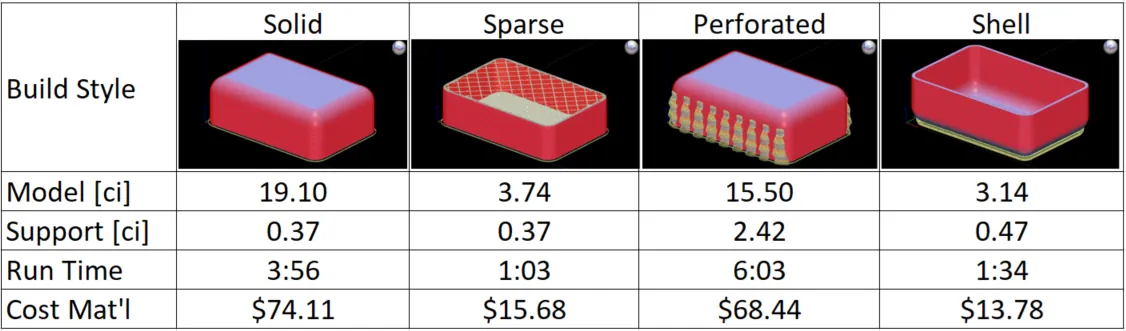
Table 1: Comparison of Material Reduction Techniques.
A Customer Application Story
A potential customer of GoEngineer was looking for a low-cost quick-turn solution to reproduce some legacy hydroform (rubber pad press) tooling. At first glance, the numbers didn’t quite pencil out. The materials cost associated with 3D printing this large bulky tool made it more expensive than their current all-in cost for machining out of Ren board. Using the shell and backfill technique above, we were able to reduce material costs for the tool. This made all the difference in helping them build a case for ROI on the system.
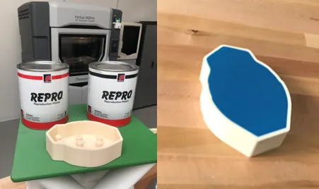
Figure 1: Materials used to fill empty shell (left) and finished product (right).
The comparison table below illustrates the savings realized by replacing the $3.80/ci ABS model material with $0.35/ci structural epoxy. In addition to producing a far cheaper version, the decreased print time means they would be able to tackle almost twice as many projects than the solid printing approach that was initially explored.
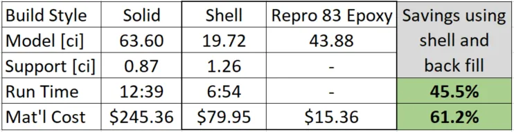
Table 2: Savings obtained using shell and backfill approach to material and runtime reduction.
For this application, we used a product called Repro 83 available from Freeman Mfg. & Supply Company. After mixing the A and B components in a 1:1 ratio and pouring that into the empty 3D printed shell, it was a quick set (less than 1 hour.) It provided a structural backbone capable of withstanding forming pressures exceeding 3000 psi.
Do you want to learn how to use this technique and others to further reduce the costs associated with 3D printing? To speak with an expert, please contact us.
More 3D Printing News
Coming Soon! Updated Print Heads from Stratasys
3D Printed Topographical Map Project: Preventing Future Flood Damage in Mid-Michigan
Stratasys' 'BIG' Release: Meet the F770

About Mark Bashor
Mark Bashor holds a Bachelor of Science in Mechanical Engineering from the University of California, Riverside. He was formerly a Sr. Applications Engineer for Stratasys and has prior experience in the aerospace and manufacturing industry. Mark has been helping customers successfully execute their additive manufacturing strategies for over 10 years.
Get our wide array of technical resources delivered right to your inbox.
Unsubscribe at any time.