Thermal Analysis Using SOLIDWORKS: FEA vs CFD
What Methods Can I Use to Solve Thermal Analysis Problems?
If you are considering a problem involving thermal analysis, SOLIDWORKS has two tools that you can use. SOLIDWORKS Simulation (FEA software) and SOLIDWORKS Flow Simulation (CFD software) are both capable of solving heat transfer and thermal analysis problems.
What's the Difference Between FEA and CFD?
Both CFD and FEA can perform analysis for all modes of heat transfer. That is conduction, convection, and radiation. However, the FEA tools require user input for the convection and radiation heat transfer coefficients. CFD can simulate the heat transfer rate between solids and fluids and the radiation to and from bodies within the simulation or external radiation sources.
So, Which One is Best?
Short answer: it depends. Theoretically, you can achieve the same results using either software when considering the heat transfer and solid body temperatures.
Long answer: SOLIDWORKS Flow Simulation will, in most cases, give the most complete solution. Both CFD and FEA from SOLIDWORKS provide results for conduction using only the material and simulation properties.
The CFD software can determine the heat transfer rate from convection and radiation, while the FEA software requires user inputs for convection and radiation heat loss values. This can be problematic for transient problems where the heat transfer behavior changes over time.
At best, these inputs will be accurate for simple, steady-state problems, provided the user has put in the work to get correct answers.
Why Would I need CFD if I Already Have FEA?
When creating a simulation that involves heat transfer, I would ask the following questions:
- Are you looking for results that consider convection (forced or natural) that changes with the design?
- Are you considering any transient effects?
- Is thermal expansion NOT going to cause significant stresses?
- Do you need to work with SOLIDWORKS Flow anyway?
- Do you need to perform many thermal analyses?
- Do you need to perform thermal analyses on complex assembly?
- Do you need to simulate heat exchangers, heat sinks, electronic cooling, or lighting systems?
If you answered yes to any of these questions, you should consider SOLIDWORKS Flow for your thermal analysis tool.
Examples Using CFD and FEA
Below are two examples. The FEA analysis tool is best in the first example, at least for the first pass analysis. I have performed studies using both the FEA and CFD tools in SOLIDWORKS on this example to emphasize the differences. In the second example, the CFD tool is the better tool, and I will show and compare the CFD and FEA results.
Example One
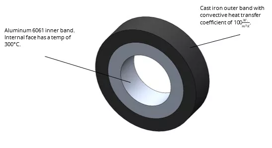
For the first example, I modeled two concentric metal bands. The interior band was 6061 aluminum and the outer band was cast iron. The internal face of the aluminum band was set to a temperature of 300°C, and a convective heat transfer coefficient on the outer wall of the iron band was roughly estimated and set to 100 (this approximates the outside passing through a blast freezer at -120°C with airflow around 45 m/s).
The temperature distribution on the concentric bands is shown below. This can then be applied as a temperature load on a static study.
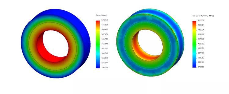
I then created a static study, fixing the outer face and importing the thermal load from above. The stress results are shown above. The ultimate strength of aluminum 6061 is 291 MPa. As you can see, the stress on the concentric bands after the simulation is well above 291 MPa on most of the assembly. I have created a second plot where the ultimate strength of aluminum 6061 is set as the maximum stress value, and anything above will be colored dark red.
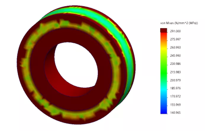
This set of parts would fail and require a redesign if no changes were made to the setup.
Now for the Flow Results.
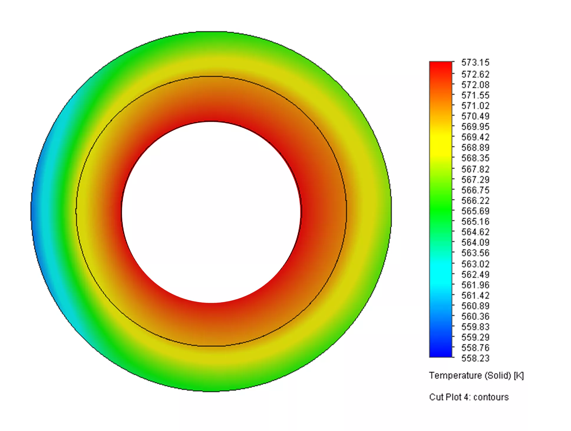
Notice that the minimum temperature value is similar to what FEA predicted. Flow predicted a minimum temperature of 558 K. In contrast, the FEA tool predicted a minimum temp of 555 K.
One benefit of the CFD tool, in this case, is we didn't have to depend on rough (lazy) guesswork to find the convective heat transfer coefficient. SOLIDWORKS Flow Simulation has heat transfer coefficient as a solver goal, and in this case, the CFD simulation gave us a value of 79.9.
The CFD tool gave us some thermal information that we didn't get from the FEA tool, namely, realistic temperature distributions and an actual heat transfer coefficient. The temperature distribution was not crucial for this design, so it wouldn't help the designer. Critically, FEA seamlessly gave us temperature-induced stress values, which showed that this part needs to be redesigned, something CFD can not do independently.
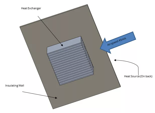
Example Two
For this example, I made a simple assembly with a heat source, wall, and heat exchanger. The heat source on the back of the heat exchanger produces 150 W with air moving over and through the heat exchanger at 45 m/s.
The surface temperature results are shown below and show the complex temperature distribution that may allow us to make better decisions when considering changes in the heat exchanger design.
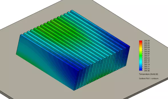
I cheated a little bit here and used the heat transfer rates and heat source temperature from the CFD results to produce the plot below. One significant benefit of using the CFD tool is that I didn't have to do the calculations myself to find these values. The CFD tool can do it.
Notice that the temperature distribution does not show the complex behavior of the more accurate CFD results. Additionally, the stresses on the parts are significantly under the yield strength of Aluminum.
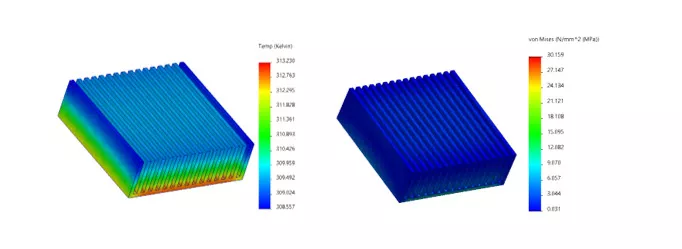
So, while you can get the thermal result from the FEA tool on something like this, it lacks the detailed results that enable the designer to make educated decisions. The temperature variation is also slight enough that we don't get any significant stress from the thermal load.
Conclusion
Both SOLIDWORKS thermal analysis tools can be used to solve a myriad of problems. The CFD tool in SOLIDWORKS Flow can find the heat transfer rates and coefficient that the FEA tool (Simulation) requires as user inputs. So, when complex fluid behavior interacts with the heat transfer of a design, SOLIDWORKS Flow is the tool to use. If thermal expansion is a consideration, SOLIDWORKS Simulation will be necessary.
It is essential to mention that Flow and Simulation can work in conjunction, and Flow analyses can be imported to Simulation to run FEA.
Related Articles
Understanding Flaps Using SOLIDWORKS Flow Simulation Parametric Study
Understanding Thermal Expansion with SOLIDWORKS Simulation
SOLIDWORKS Flow Simulation Transient Pressure Pulse Study
How to Set Up a Thermal Study in SOLIDWORKS Simulation Professional
Understanding the Tesla Valve Using SOLIDWORKS Flow Simulation

About Andrew Smith
Andrew Smith is an Application Engineer and Simulation Specialist at GoEngineer. Andrew earned his bachelor’s degree in mechanical and aerospace engineering and his master’s degree in mechanical engineering at Utah State University, where he wrote his thesis on baseball aerodynamics and discovered the Seam-Shifted-Wake. He is passionate about engineering, fluid dynamics, and simulation and loves helping others find the best engineering solution for their problem. When not working, Andrew can be found reading crag-side or mountain biking with his family.
Get our wide array of technical resources delivered right to your inbox.
Unsubscribe at any time.