Using the Move/Copy Body Feature in SOLIDWORKS
The SOLIDWORKS 'Move/Copy Body' command is an efficient way to get a model reoriented properly for a variety of downstream uses.
When working with imported STEP, IGES, or Parasolid imported geometry, there might be a need to reorient the model. Unlike a native SOLIDWORKS model, your choices for modifying the orientation of the imported model are limited. You cannot just change the sketch plane of the first feature and attempt to fix it so easily.
The ‘Move/Copy Body’ feature can be used reorient geometry to the default planes. This will make it easier to locate in assemblies. Reorienting a part can also help with drawing view creation or with making mold tooling.
how to Access the “Move/Copy Body” Feature
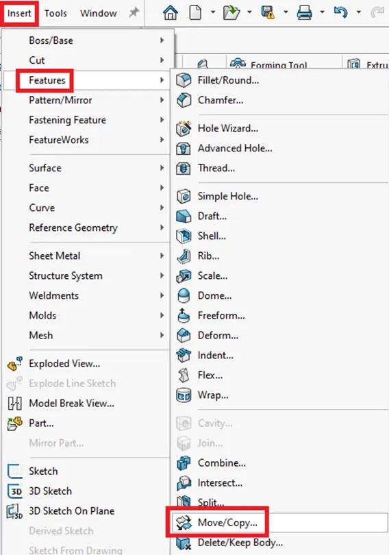
The Move/Copy Body feature is not located in the Command Manager Features Tab. In the Features drop-down menu, navigate to Insert > Features > Move/Copy…
This feature works with both solid and/or surface bodies. Check the ‘Solid’ and ‘Surface Bodies’ folder in the FeatureManager Design Tree to get a better understanding of what type of geometry you are working with. This will show you how many solid or surface bodies are in a native SOLIDWORKS file or an imported model.
When using the 'Move/Copy Body' feature, first select the solid or surface body(s) to move. Select the desired body(s) from the graphics area or from the Solid or Surface Bodies folders. As shown below, ensure the "Copy" option is unchecked so that you only move the geometry and not duplicate it.
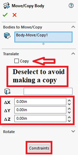
Highlighted above in the lower two red boxes are the two ways to move the bodies, Translate/Rotate or Constraints. The 'Constraints' option is very similar to using the standard assembly mates. Just as when mating components in assemblies, three mates/constraints can fully define the orientation of prismatic bodies.
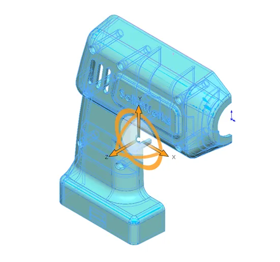
The Translate/Rotate option will show a large, orange triad (shown below) that can be used to manipulate the orientation of bodies. The geometry can be manipulated by dragging the arrows or circles or by entering values into the dialog boxes. You can translate in multiple directions in one step or feature but you cannot translate and rotate in the same feature.
In this example, we use the 'Constraints' option with three default planes and a combination of geometry entities to get the desired orientation, moving the origin into the lower left-hand corner. Step 1 uses the Right Plane and lower back vertex as shown below.
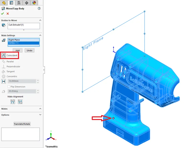
Step 2 will rotate the model 90 Degrees. This can be done in several ways. One intuitive way is to use the 'Constraint' option with a bottom face making it Coincident to the Top Plane as shown below.
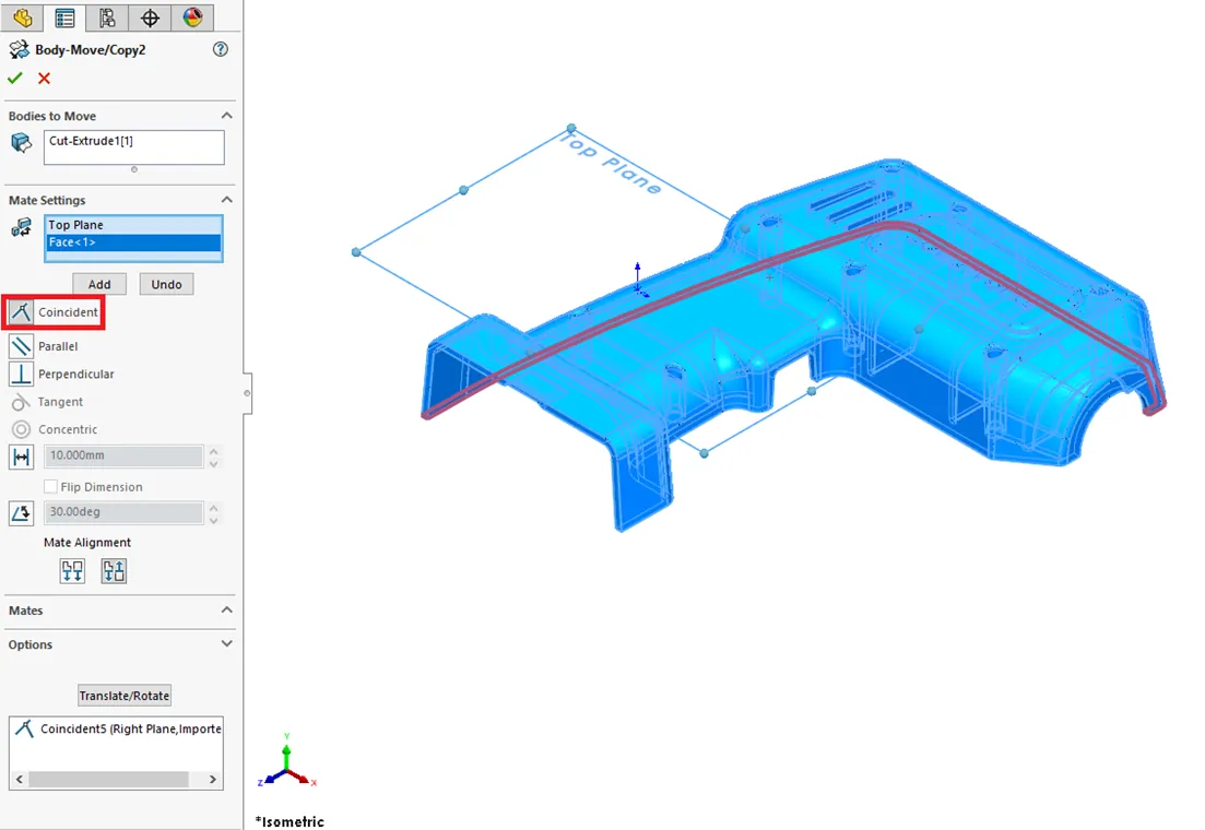
You can add several 'Constraints' in the same command, just remember to select 'Add' to lock in each constraint.
The final step shows that you can use the Origin as a point for one of the constraints just like in a regular assembly mate. This final action gets the origin placed in the lower-left corner.
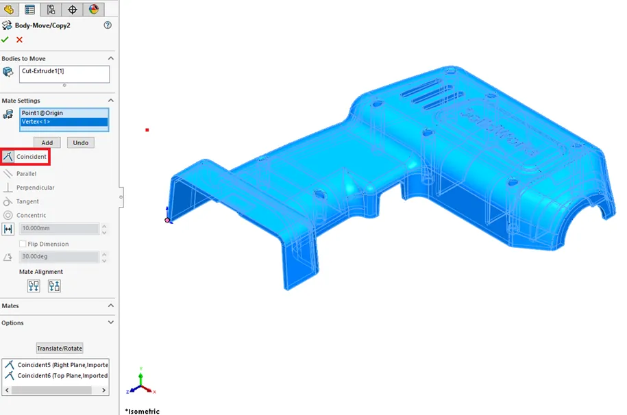
The Front Plane could have also been used for this step. Vertices or edges can be used when a flat face might not always be available. After selecting 'Add' for the third time, this locks in all three 'Constraints' into one 'Move/Copy Body' feature. This feature acts as a point in time and can be modified by selecting 'Edit Feature'.
Move/Copy Body Limitations
As mentioned above, the 'Move/Copy Body' feature will not allow you to translate and rotate in the same step or command. The good news is those types of orientation changes can easily be broken up into multiple features.
The last thing to know is that 'Move/Copy Body' does not allow a combination of reference geometry as constraints to be added in an imported part. If you see this warning “Please select an entity from one of the moving bodies” select a vertex, edge, or face if possible. You will not be able to use an axis or reference plane with another plane for constraints.
In other words, you can only use one reference plane and an edge, face, or vertex. Worst case scenario would be to use a combination of constraint and translate/rotate 'Move/Copy Body' features to get the desired orientation. Another workaround might be to add a small extrusion and use a face, edge, or vertex from that geometry and then remove the extra geometry with a cut or ‘Delete Face’ command.
Conclusion
The SOLIDWORKS 'Move/Copy Body' feature can be used multiple times and can be suppressed/unsuppressed manually or in configurations. As mentioned before, this command works with both solid and surface bodies and can be used to duplicate geometry similar to the ‘Linear Pattern’ feature. This command can help quickly reorient your imported models for easier assembly, drawing or mold tooling creation, or CAM setup.
Our Newest SOLIDWORKS Tutorials
Link a Dimension to the BOM with a Custom Property
Searching for Functions in SOLIDWORKS 2021
How to Install and Troubleshoot Fonts in SOLIDWORKS

About Maurice Cherian
Maurice Cherian is Technical Support Engineer at GoEngineer. He was introduced to CAD while working for the Navy. Maurice has over seventeen years of Software Training and overall CAD experience. He has been using SOLIDWORKS since 2008 and is a certified expert and instructor. He provides SOLIDWORKS training and Tech Support. Maurice is active in the SOLIDWORKS User Group Community in San Diego, presenting and hosting multiple times over the last eleven years.
Get our wide array of technical resources delivered right to your inbox.
Unsubscribe at any time.