Using Thermal Boundary Conditions in SOLIDWORKS Simulation to Simulate a Press Fit Connection
Simulating a press fit condition in SOLIDWORKS Simulation can be very challenging when there is a large amount of interference between interfacing components. This type of analysis requires a nonlinear study to capture the large deformations induced by the press fit. There is a no penetration contact condition that can be used for simulating press fit connections. It is referred to in the software as a shrink fit condition.
Related Article >> No Penetration Contact Set Setup
When running a nonlinear analysis or a linear static analysis with the large displacement option enabled, the solver will solve for the shrink fit condition in the first time step. Depending on the amount of interference, there are situations where the solver cannot successfully perform the calculation.
In these cases, the press fit condition has to be simulated through other means. Another approach is to apply thermal boundary conditions to simulate the contraction and expansion of the interfacing components. This article will cover the workflow of using thermal boundary conditions to successfully simulate a press fit connection when the shrink fit boundary condition is unsuccessful.
Model Specifics
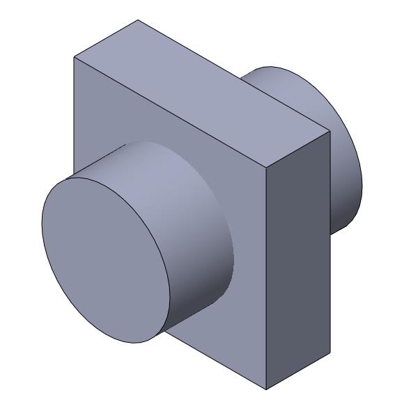
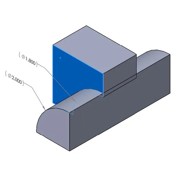
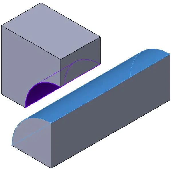
In this example, the analysis involves a 2-inch diameter round shaft press fit into a bracket with a 1.9 inch round hole. Since the model and the loading are quarter symmetric, a quarter of the model will be used for the analysis setup.
Nonlinear Analysis with Shrink Fit No Penetration Contact Condition
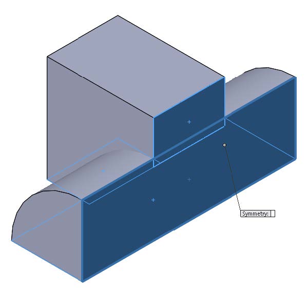
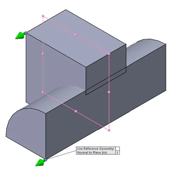
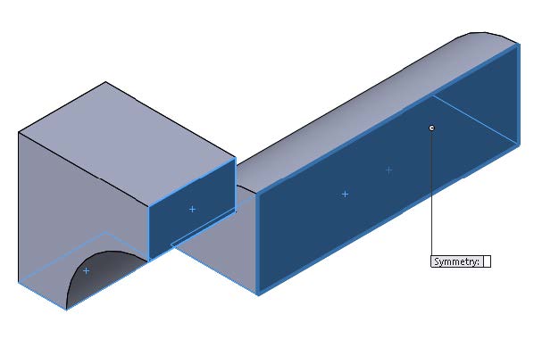
Two fixtures were applied to the model. A symmetry fixture was applied to the four surfaces created by the symmetry cut. This fixture restrained two degrees of freedom. To restrain the third degree of freedom and prohibit rigid body motion, a use reference geometry fixture was applied to a single vertex on each component to limit the axial translation. A plane was used for the reference entity and the normal to plane translation was set to zero. A shrink fit no penetration contact set was set up between the cylindrical faces of the interfacing components.
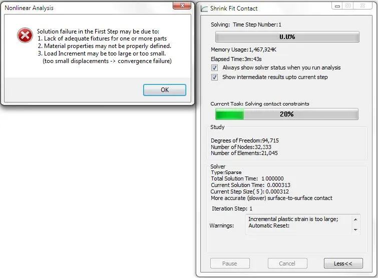
The analysis failed due to the large interference between the interfacing components. The warning displayed in the nonlinear solver dialog window was: Incremental plastic strain is too large; Automatic reset. There was too much displacement in the initial time step for each component and the solver could not satisfy equilibrium constraints.
Nonlinear Analysis with Thermal Boundary Conditions
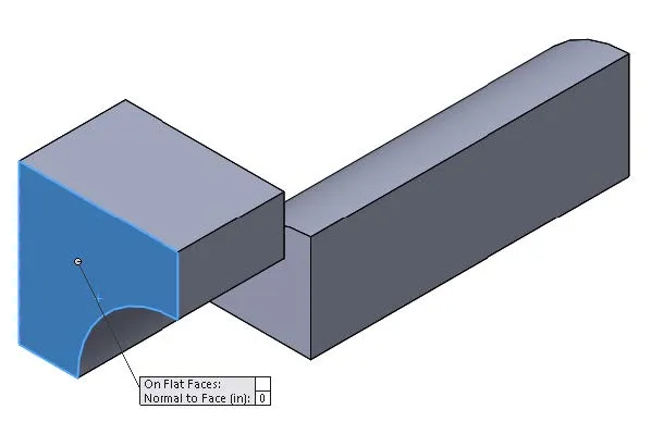
In this analysis setup, the shaft was moved axially so that there was no initial contact between the components. A symmetry fixture was applied to the four surfaces created by the symmetry cut. This fixture restrained two degrees of freedom for each component. To restrain the third degree of freedom for the bracket model, and flat face fixture was applied to one of its surfaces restraining the movement in the normal direction.
A temperature load was applied to the bracket body heating it up from 75 °F to 500 °F. The purpose of this load was to expand its hole to be larger than the shaft diameter. The reference temperature at zero strain study setting was set to 75 °F. This specified that there were no displacements caused by thermal loading at 75 °F. The thermal expansion coefficient for the bracket material was increased so that the body would more easily thermally expand. A time curve was set up to control the heating and cooling of the bracket component.
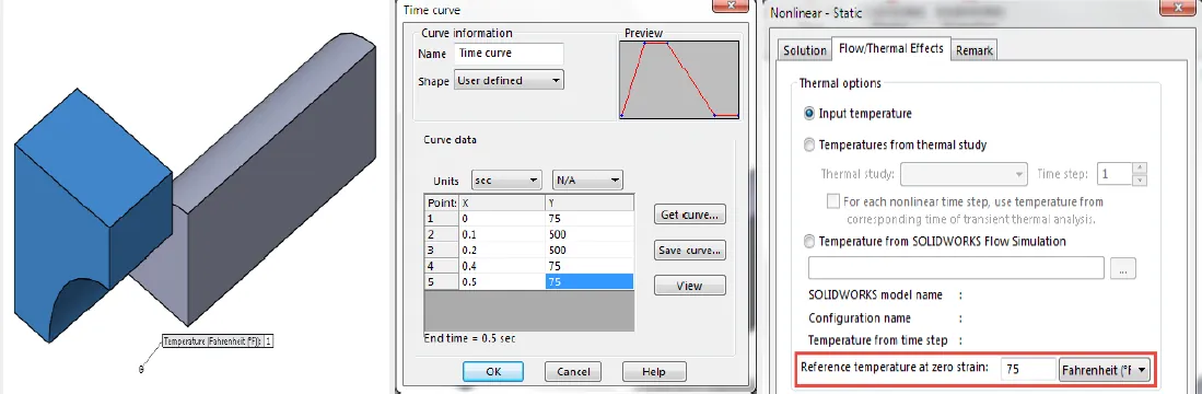
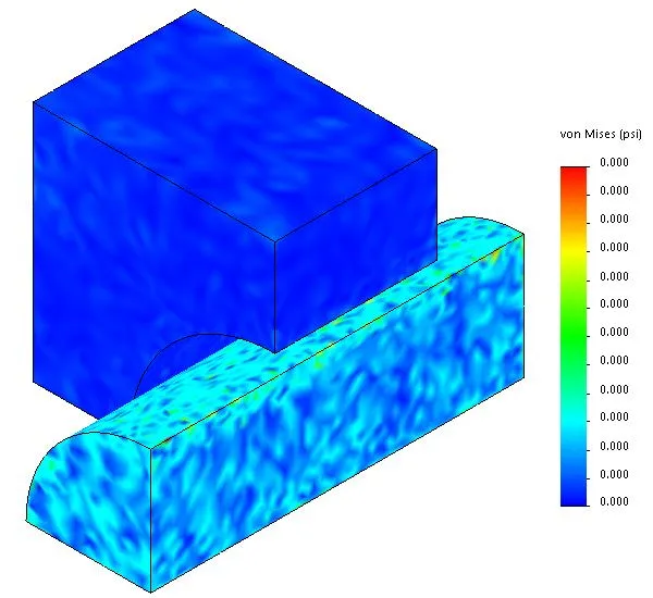
Since the component was not restricted from thermally expanding in any direction, the von Mises stress magnitude after the bracket was heated up to 500 °F was zero.
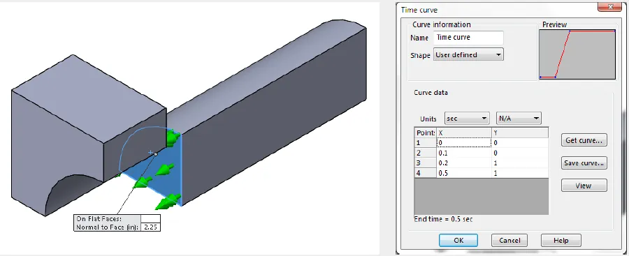
After the bracket was heated up to 500 °F, the shaft was moved axially to be centered within the bracket hole. This was accomplished by using another flat face fixture applied to one of the shaft surfaces. It was held stationary until the bracket was heated to 500 °F and was then moved into position through the use of a time curve. The temperature of the bracket component was then gradually decreased inducing contact between the bracket and the shaft allowing for the shrink fit connection to develop.
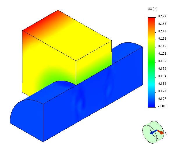
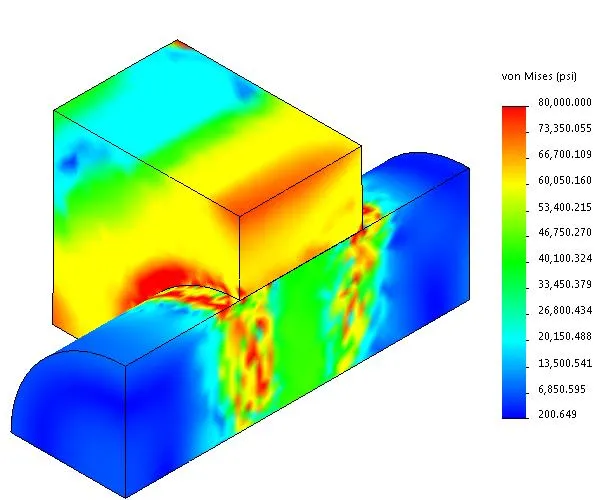
The following screenshots display the radial displacement and von Mises stress after the thermal load has been removed from the bracket component.
Expand your SOLIDWORKS Simulation Skillset
Performing a Thermal Stress Analysis in SOLIDWORKS Simulation
Time-Based Thermal Stress in SOLIDWORKS Simulation
Troubleshooting SOLIDWORKS No Penetration Contact Sets Recommendations
![]()
About GoEngineer
GoEngineer delivers software, technology, and expertise that enable companies to unlock design innovation and deliver better products faster. With more than 40 years of experience and tens of thousands of customers in high tech, medical, machine design, energy and other industries, GoEngineer provides best-in-class design solutions from SOLIDWORKS CAD, Stratasys 3D printing, Creaform & Artec 3D scanning, CAMWorks, PLM, and more
Get our wide array of technical resources delivered right to your inbox.
Unsubscribe at any time.