3D Printed Redesign of Corvette C4 Gas Pedal Mount
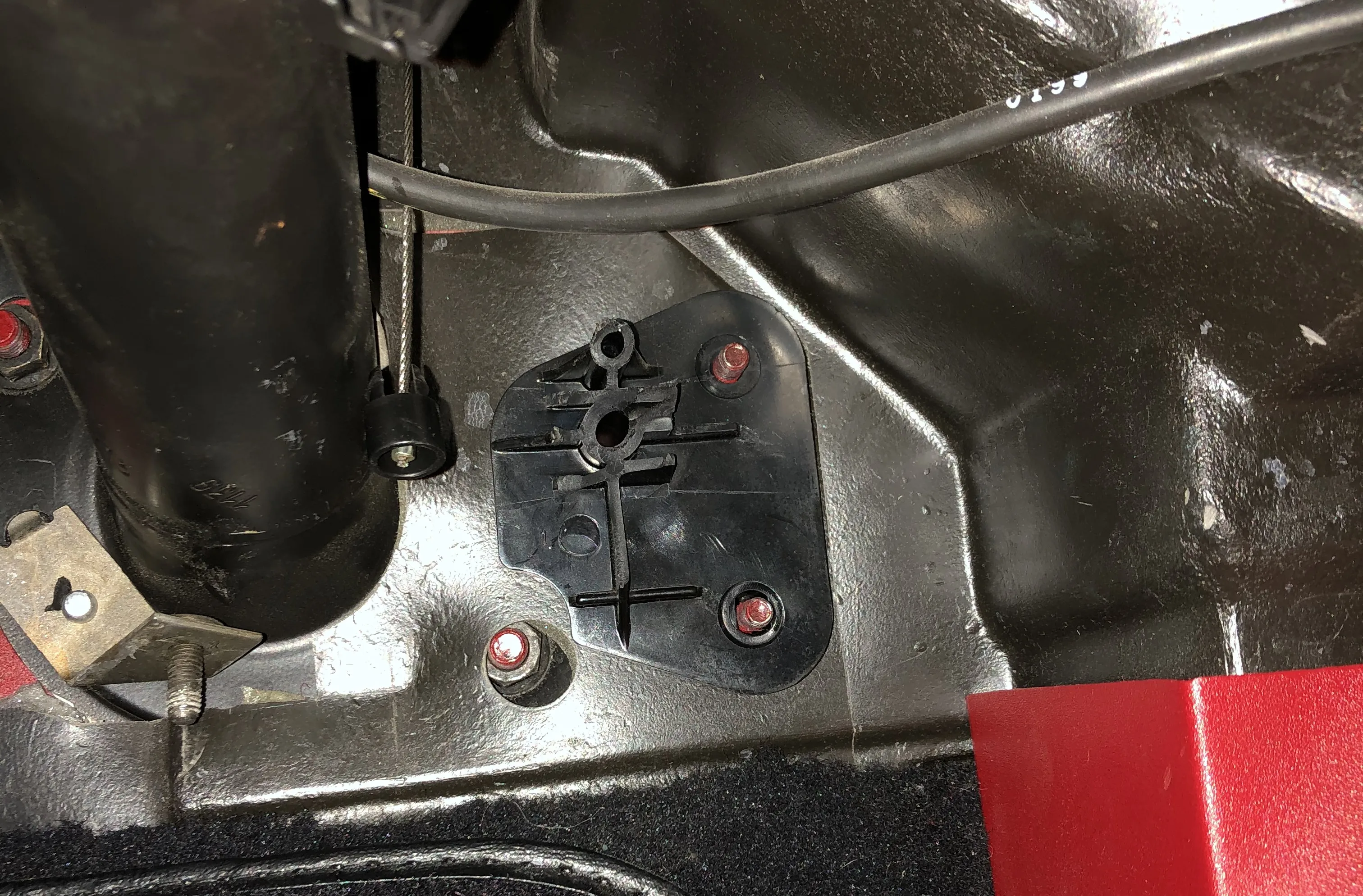
My colleague Tyler recently picked up a C4 Corvette. As with any 'new-to-you' car, there are a few customary 'performance checks' to conduct prior to day-to-day driving. During one of these routine performance checks (rumored to be a parking lot donut), the gas pedal experienced abnormal sideload and stress, ultimately causing a failure in the gas pedal hinge (pictured below). What you can see are sheared support ribs and what you can't see is the pedal assembly...because it broke off!
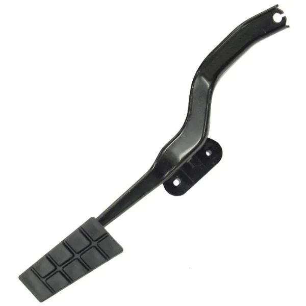
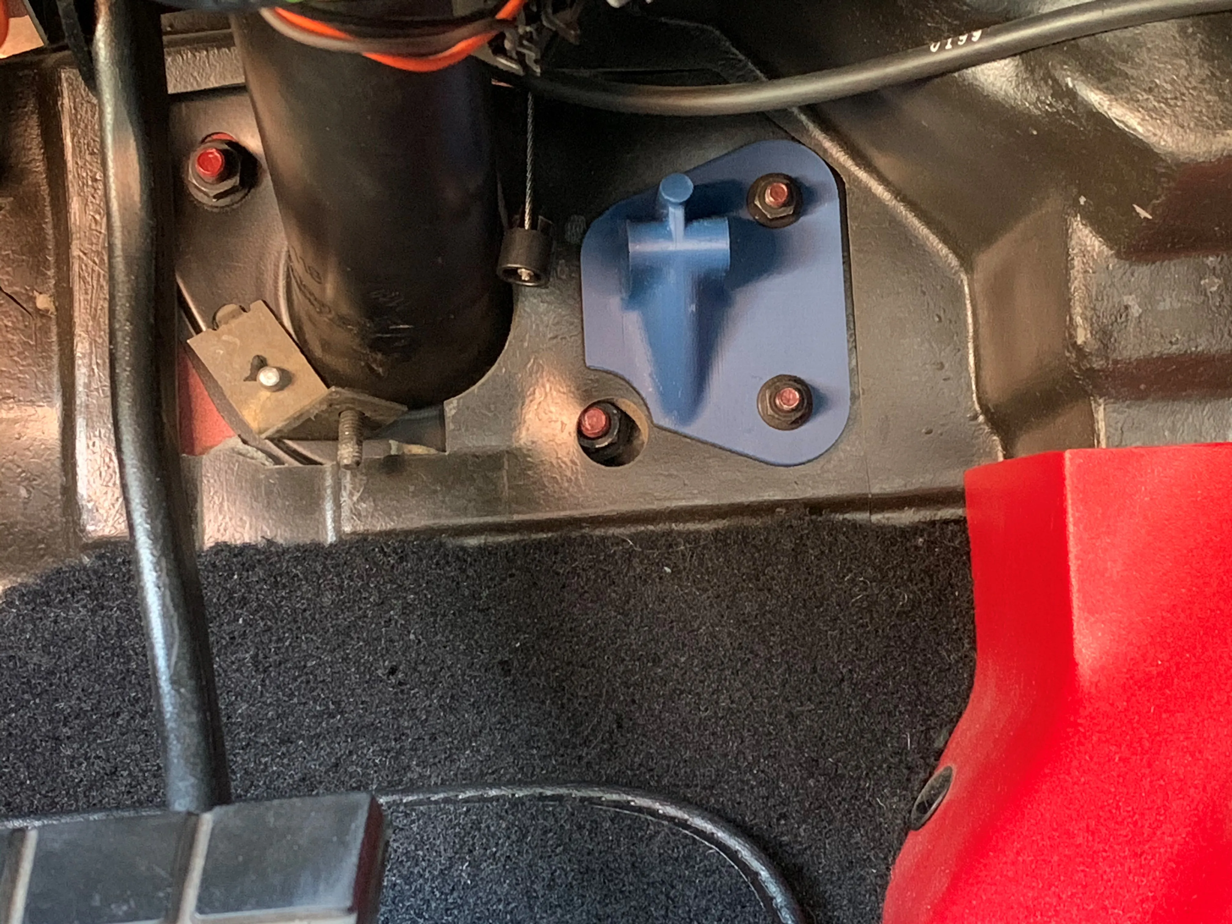
Here's an example of how the part should look like if it hadn't failed.

This is how the unit looks like as a whole assembly.
Why did it fail?
During the routine performance check (aka donut exercise), some side-loading may have occurred at about the time Tyler exceeded 1G on the skidpad. In all fairness, the part wasn't likely designed with these stresses in mind and as we found out, Tyler isn’t the only donut aficionado. According to Google, other people have reported experiencing the same failures.
So the part failed due to higher than normal stresses on a part that had limited material in crucial stress zones. Why wasn't the part designed with more material? The lowest common denominator is price - it's not uncommon for engineers to be given cost constraints, time constraints, and volume goals. All these constraints determine feasible manufacturing processes which may lead to concessions in the overall functionality/strength. (I'll talk about this more later)
Traditional Manufacturing Processes – Injection Molding
Approximately, 20,000-50,000 C4 Corvettes were sold per year for over a decade. When dealing with that volume of production, injection molding becomes a no-brainer. The cost of a mold quickly gets eaten up when it’s divided among more parts. Low cost per part, a wide array of thermoplastics, and the potential for multiple years of use make injection molding a great choice. Check this short clip out for a quick animation of the injection molding process.
The primary hurdle of injection molding is the startup cost. Because it is so expensive to produce a production mold (roughly 10k for a single-part mold, this size, produced overseas), it takes extremely high quantities and/or a very long timeline to justify the cost. The high costs don’t end there either. Imagine getting a mold produced overseas, waiting for it to ship, receiving it, and testing it just to find out it needs a revision. Stop production, send it back, wait for rework, and then wait some more for it to make its way back.
A common struggle for an engineer is making compromises to a design for manufacturability. The injection molding process requires consistent or near-constant wall thicknesses due to material cooling and warpage.
By now you probably understand this part’s largest pitfall was the constraint of uniform wall thicknesses inherent in injection mold design. The part is essentially comprised of a network of .100” walls. By simply filling in the network of walls the part would be strengthened, and the overall footprint would hardly change.
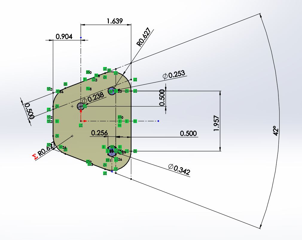
We knew how we wanted to beef it up, now it was time to make it. Armed with SOLIDWORKS and a set of halfway-decent calipers, I reverse-engineered the part. For a part like this, it was relatively simple. I like to start by creating a sketch in SOLIDWORKS that resembles the shape of the part (in this case I started with the main flange).
Then, I measure the part with calipers and fully define the sketch one measurement at a time.
Once I created the main flange adding the additional features was relatively simple.
Watch this quick snippet of how the features were added below.
As you can see, I took strengthening the part one step further than just adding material. I also added larger fillets anywhere I could afford to, based on space limitations. This helps distribute loads more evenly.
Why Additive Manufacturing solves these one-off issues so well
Because we’re not limited by the constraints of injection molding design, we become untethered from the constraints of traditional design for manufacturing. Additive manufacturing gives you the ability to design parts based more on their function than how they’re created. Additive technologies offer additional advantages too. We can change part density, shell thickness, and overall part rigidity with the click of a button or drag of a digital slider bar.
How Much Did We Spend?
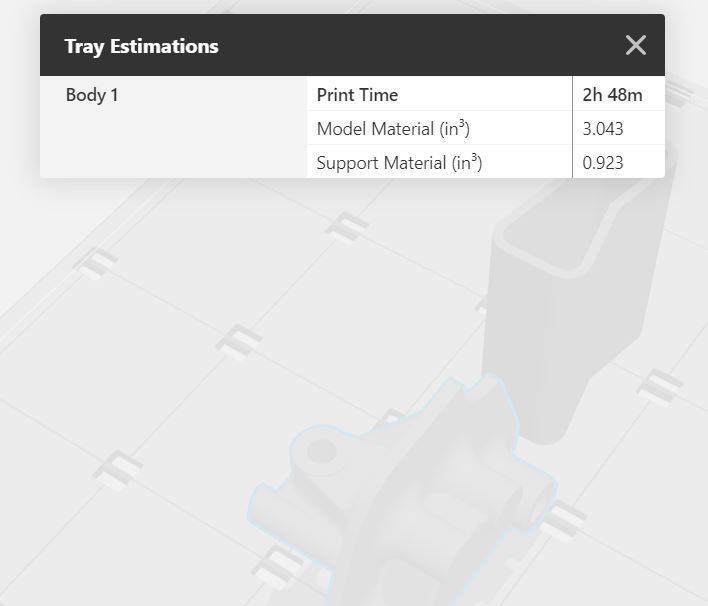
We ran up a total material bill of ≈$12. Yes, you read that right. In terms of time, I spent about 30 minutes of design and modeling time, 5 minutes of post-processing, and less than 5 minutes to load the tray/unload part. The print itself took less than 3 hours to complete.
While I don’t want to ignore the cost of labor, tools, or facility, I also want to stay away from overcomplicating things. If you’re a business owner, you likely have a good understanding of your labor costs, amortization schedules, and facility. With these figures, you may be able to determine a reasonable estimate to tac on the backside of that $12. What's great about having a 3D printer is while it was printing, it’s counterpart (me) was working diligently on other tasks.
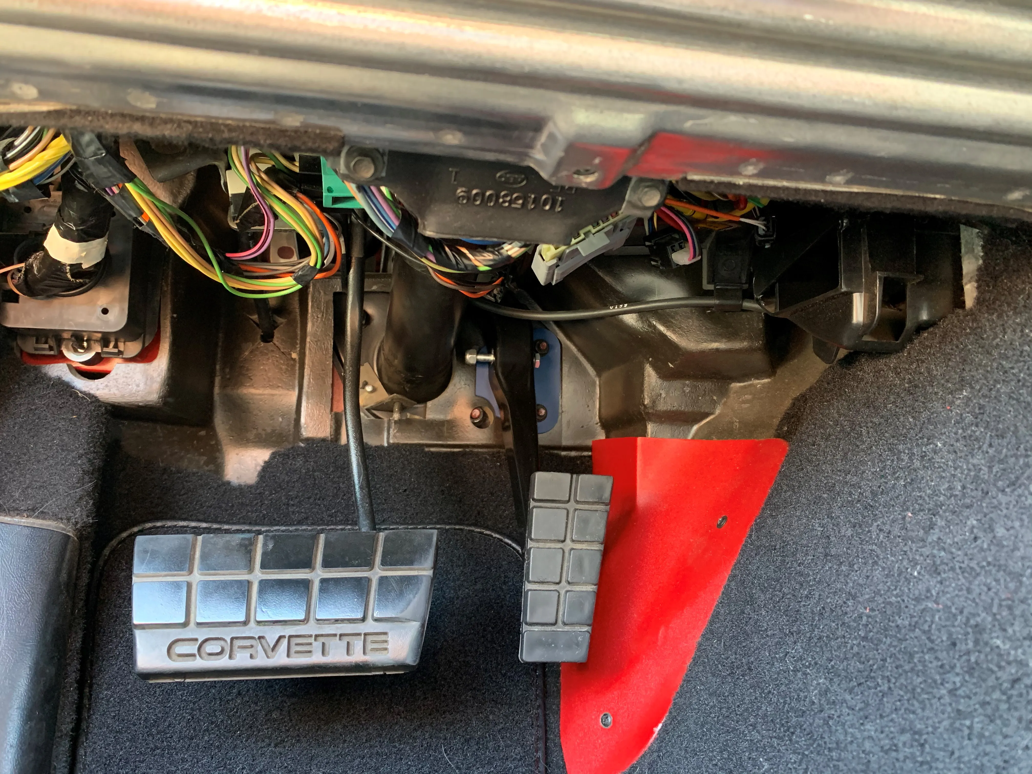
Is It Still Working?
Yes! The revised AM version of the part has been in the car for about two months now and has worked with fantastic results. Tyler claims, “I don’t even worry about it. It has worked perfectly since day one!”
Final Thoughts
As someone who has always enjoyed manufacturing processes and making my own stuff, I have gone through the wringer when it comes to manufacturing. When everything you do is a one-off, the high price of something like injection molding can be a tough pill to swallow. With the advancements in materials becoming 3D printable, there has never been a better time for people like me. We can now make usable prototypes for less money, in less time, and with fewer constraints than ever before.
Check out more of our 3D hacks and design projects below.
More Projects
3D Printed Trim Panel for Custom Shifters
Prop Guards for Drone Propellers
A Modern Take on a Classic: 3D Printed Fender Telecaster
3D Printing & Controlling a 6-Axis Robotic Arm
Designing a 3D Printed Storage Box Using Multi-Body Part Modeling in SOLIDWORKS

About Tate Brown
Tate Brown is a Manufacturing Applications Engineer at GoEngineer. He has worked with Novatek and Schlumberger in a partnership working with their intellectual property team developing and prototyping improved down-hole systems as well as other industry leading technologies. Just prior to joining GoEngineer, Tate worked with Rooftop Anchor helping in the design and testing of suspended access systems used by window washers and service crews on skyscrapers.
Get our wide array of technical resources delivered right to your inbox.
Unsubscribe at any time.