3DEXPERIENCE Fluid Dynamics Engineer: Simple Internal Flow
3DEXPERIENCE FLUIDS Fluid Dynamics Engineer is a high-power tool that allows the user to create, modify, and run Computational Fluid Dynamics (CFD) simulations. It is a general-purpose CFD tool that works in the 3DEXPERIENCE environment, allowing users the benefits of cloud storage, cloud computing, and cloud collaboration.
As a quick guide to setting up a Fluid Dynamics Engineer case, we will walk through the simple internal flow example of a small electronic container without any components inside or any thermal analysis considered.
Please follow the steps in the tutorial How to Import SOLIDWORKS Parts Into 3DEXPERIENCE before continuing with this introduction.
Quick Note: Learning Assistant Panel & Action Bar
On the 3DEXPERIENCE side of things, we will follow the Learning Assistant Panel.
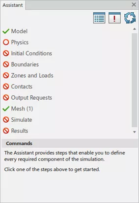
Learning Assistant Panel
The Learning Assistant Panel is a helpful tool that helps guide the user through the fluid simulation process. Experience and knowledge are required for the setup to be sufficient and to provide adequate, reliable, and realistic results. The Learning Assistant Panel should be followed from top to bottom. Several symbols indicate the state of the setup we are in.
The table below explains these symbols and their meanings.
We will be using the Learning Assistant Panel to set up this simulation, as it is a convenient way to work through the process. All of the commands and tools can be accessed from the Action Bar at the bottom of the window. The process can be completed from either the Learning Assistant Panel or the Action Bar.
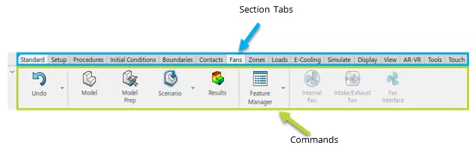
Action Bar
The Action Bar is divided into two areas. The first, shown in blue, is the Section Tabs area which opens a set of commands. The second, shown in green, is the command area.
Additional notes:
- The “Standard” Section Tab is pinned by default (but can be unpinned if desired), ensuring the standard commands (Undo, Fluid Dynamics Engineer Apps, and Feature Manager) are always available.
- The default setting of the Action Bar does not show text. Right-click the action bar to show the text and select Display Icons and Text.
![]()
Step 1: Model Setup
As mentioned above, we will follow the Learning Assistant Panel to set up this basic internal flow case. Click the Model step in the Learning Assistant Panel to display the commands used to set up the model.
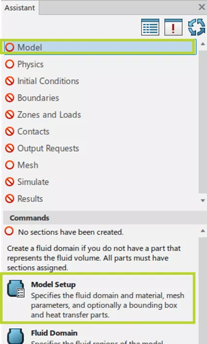
Because our case is simple, we will only need the Model Setup command, which, when selected, pulls up the following window. We are only considering the internal flow here and will not consider thermal behavior at this stage. We will leave the first two checkboxes unchecked.
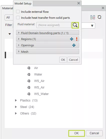
We will define the fluid used in this case by clicking the eyeglass symbol to open the Material Palette window.
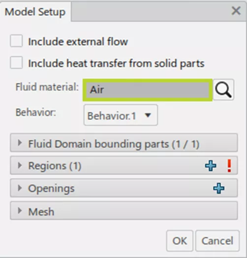
For these purposes, we only need air. To add it, select Air from the fluid pull-down and click OK. The Model Setup window now shows Air as the Fluid material.
Next, we need to select the Fluid Domain bounding parts. In this case, it is straightforward, and the default selection is sufficient. A wise selection of the correct bounding parts for more complex models will save time and computational energy.
Now to define the regions. Because we are not considering any thermal behavior, we only need to define the fluid region. To do so, click the Regions pull-down and select a face that touches the fluid.
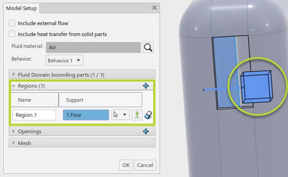
Once the face is selected, a glyph indicates the face the fluid is touching and which side of the face will define the fluid region. In this case, the blue face inside the container is selected, and the glyph shows that the region is the container’s interior.
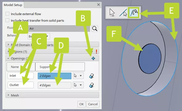
Now to define the openings. Open the Openings pull-down (“A”) and hit the blue “+” symbol (“B”) twice.
In this example, I have renamed the openings from “Opening.1” and “Opening.2” to the more appropriate and helpful “Inlet” and “Outlet” (“C”). The supports (“D”) must be defined by selecting edges that encompass the opening (we can use edge propagation) (“E”), which generates a glyph (“F”) representing the opening.
The final model setup step is to set up the initial mesh settings. I usually leave the default settings as-is at this point. We will use the more thorough meshing commands at a later stage.
For now, click the OK button to close the Model Setup window. We will now see a green check next to Model in the Learning Assistant Panel. This means that the required commands have been run for this phase of setup, and we can now move on to the physics setup.
Step 2: Physics
By clicking Physics in the Learning Assistant Panel, 3DEXPERIENCE automatically switches to the Fluid Scenario app. The Physics step specifies how fluid and solid regions behave.
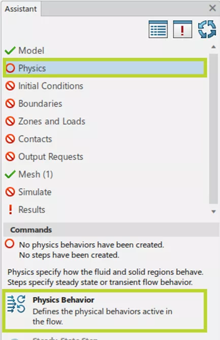
Once we have clicked Physics Behavior, we can define the physics models we will use to solve the CFD case.
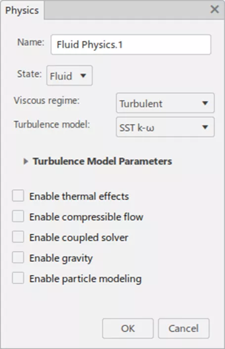
For this simple internal flow, no changes were necessary, so we can click the OK button. Future posts will cover the different turbulence models, what they are suitable for, and when these other physics ought to be enabled.
Once this step is complete, users can add analysis procedures to determine either steady-state or time-dependent solutions. Multiple steps can be set up to run sequentially.
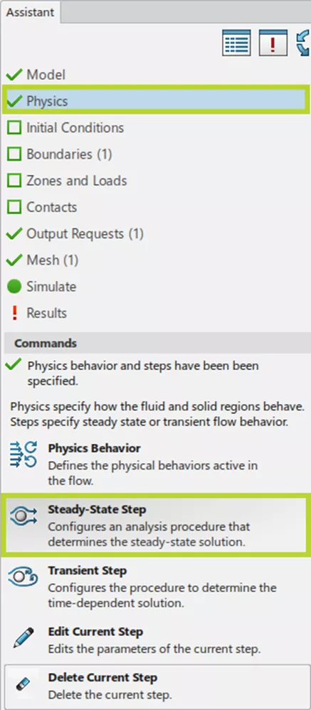
The Steady-State and the Transient Steps command windows are shown below. (In this case, we will set up a Steady-State step)
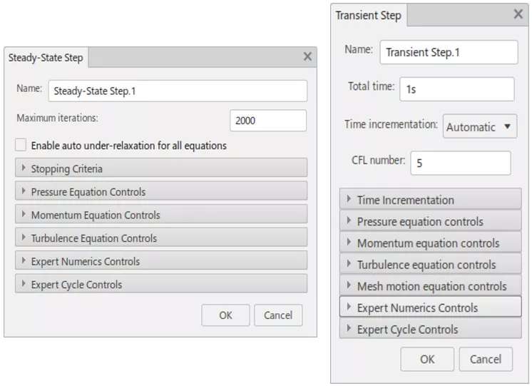
Once this step is finished, we can run the simulation. Lacking boundary conditions, this result would be a bit dull. Fortunately, we still have some steps left to take.
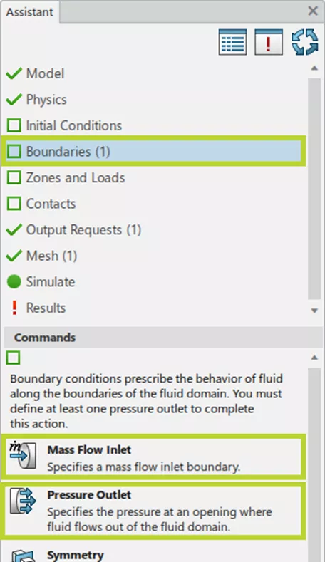
Step 3: Boundary Conditions
Boundary Conditions are the meat and potatoes of a simulation. In this case, we need an inlet and outlet to match the inlet and outlet defined in the Model Setup step.
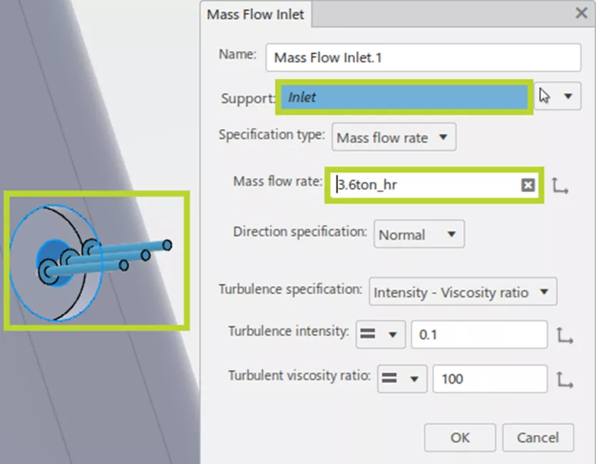
Following the same pattern outlined above, we select the Mass Flow Inlet command. Where we can choose the Inlet glyph as the support. For some reason, the default units here are Metric Tons/Hour. (Note: 3.6 Tons/Hour = 1 kg/sec.)
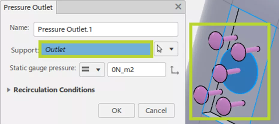
We follow the same process for the pressure outlet.
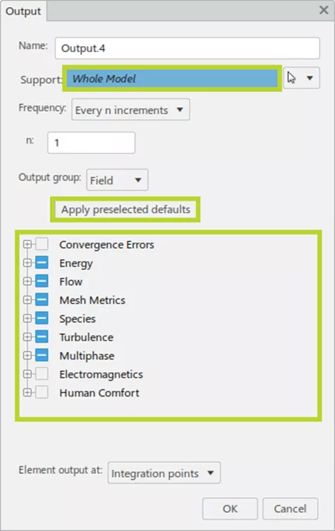
Step 4: Output Requests
The decision-making power of simulation comes from the result outputs. While this topic is of critical importance, it is beyond the scope of this post and will be covered only briefly.
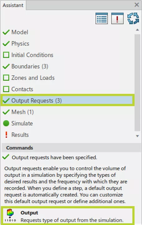
Some output types are set as the defaults; if we request no output types, these will be generated automatically. This list can be seen by checking the Apply preselected defaults button. Otherwise, we can choose custom output types (which will be dependent on the support we choose).
Step 5: Mesh
This may be the most crucial step we need to accomplish and deserves its own post. For now, we will walk through the basic meshing procedure.
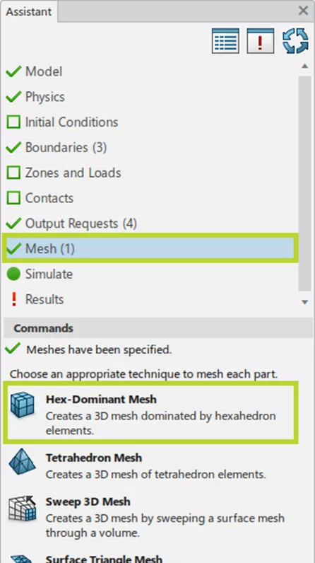
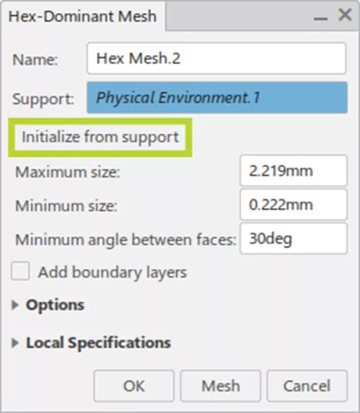
Hex-Dominant Mesh is the recommended mesh strategy (and the one we will choose here). Doing so reveals the Hex-Dominant Mesh window. Selecting the Initialize from support button from this window modifies the Maximum and Minimum size options based on the geometry we are analyzing. Click the Mesh button and allow the meshing process to complete.
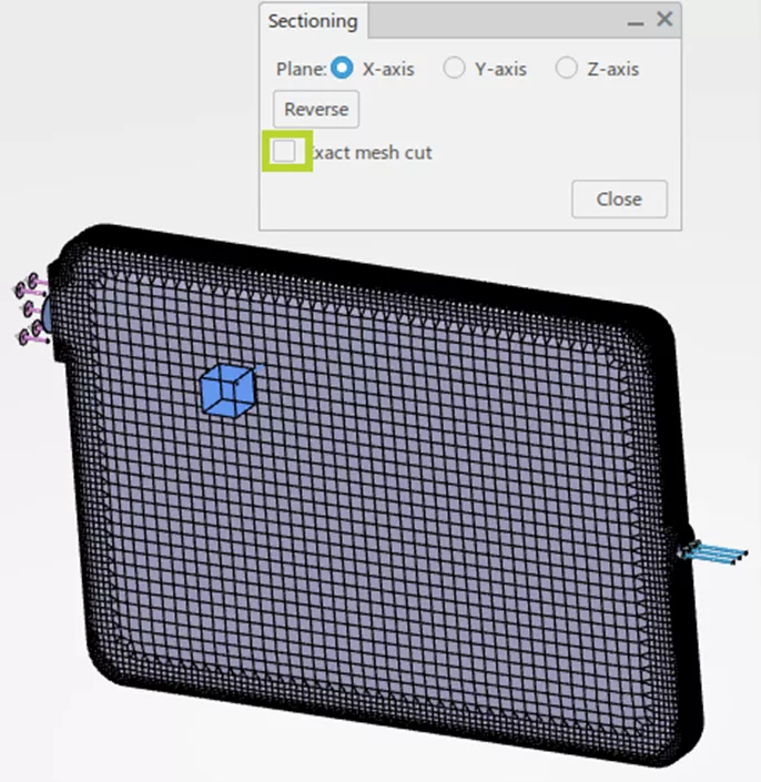
View the internal mesh by selecting the Sectioning command within the Display section tab and unchecking the Exact mesh cut checkbox.
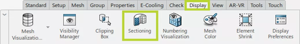
Notice that the cells are the minimum size near the walls and grow to the maximum size in the internal area.
This is the final step before we can begin the solver and is a key step that plays a significant role in the solution.
Step 6: Simulate
Continue to follow the same pattern as before.
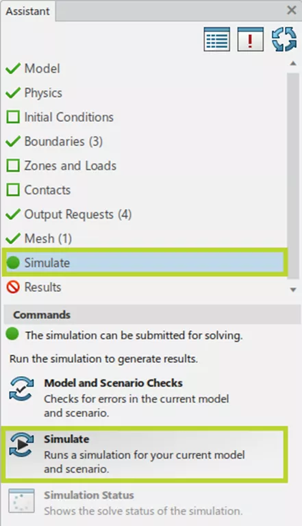
Run the Model and Scenario Checks command to ensure we have everything required to run the simulation successfully. (These run automatically when we run the Simulate command.) We can then select the method for running the solver and the number of cores. 3DEXPERIENCE grants up to 16 free cores (either local or cloud) for solving the simulations.
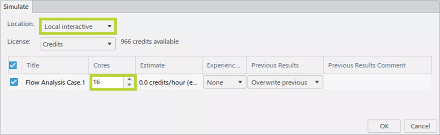
Once we hit the OK button, the Simulation Status window opens and shows the progress of the simulation.
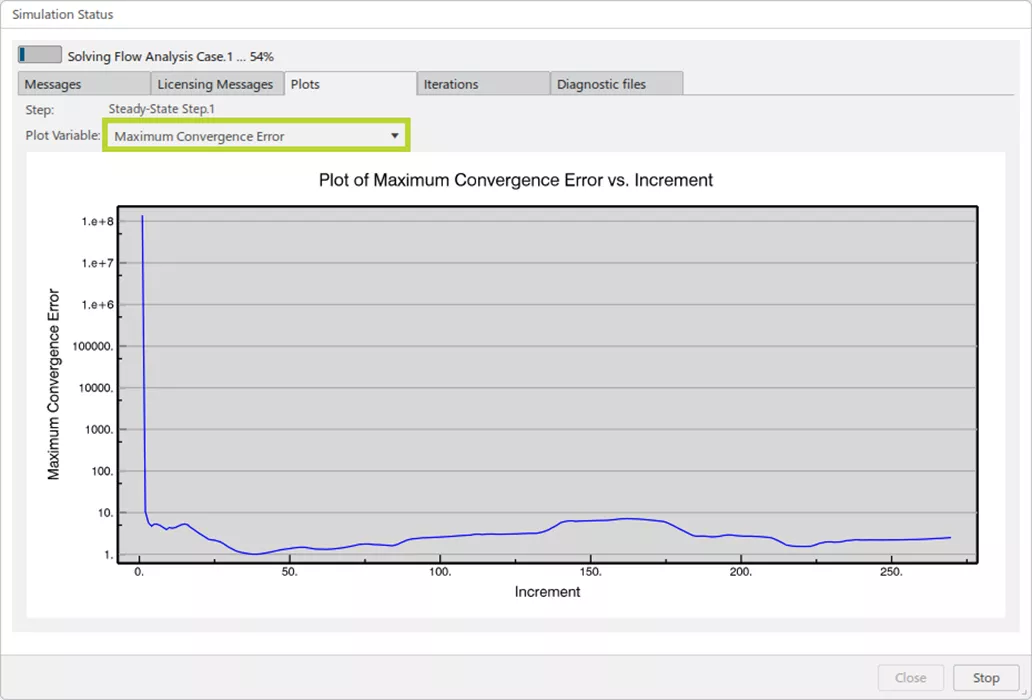
The solver will complete when it achieves the appropriate residual error or the maximum number of iterations.
Step 7: Results
When the solver finishes, 3DEXPERIENCE will automatically switch to the Results app. This also deserves its own post, but the long and short of it is this: only the outputs requested in step 4 above can be displayed. The plots window will automatically open, and we can change the plot type from here.
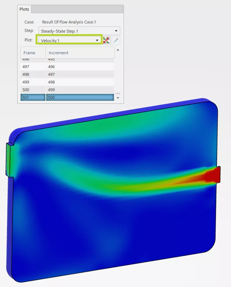
To look at a cut plot, like above, follow the same process by selecting the Plot Sectioning button in the Display section tab.
Conclusion
The Fluid Dynamics Engineer tool on 3DEXPERIENCE is a powerful, general-purpose tool for running CFD simulations. This post explained the basic steps for running these analyses. The Learning Assistant Panel helps users follow the procedures to set up and run simple to complex simulations with thermal effects, gravity, free-surface flows, and more. Utilizing cloud computing, collaboration, and cloud storage will enhance the ability of an analyst to find and communicate results and make effective design decisions.
Want to learn more? Check out more 3DEXPERIENCE Simulation tutorials below.
Related Articles
Why Use Hex Elements in Your FEA?
Create 3DEXPERIENCE Simulation Study Search Widget
3DEXPERIENCE Platform Beam Analysis
CST Studio Suite for Electronic Design

About Andrew Smith
Andrew Smith is an Application Engineer and Simulation Specialist at GoEngineer. Andrew earned his bachelor’s degree in mechanical and aerospace engineering and his master’s degree in mechanical engineering at Utah State University, where he wrote his thesis on baseball aerodynamics and discovered the Seam-Shifted-Wake. He is passionate about engineering, fluid dynamics, and simulation and loves helping others find the best engineering solution for their problem. When not working, Andrew can be found reading crag-side or mountain biking with his family.
Get our wide array of technical resources delivered right to your inbox.
Unsubscribe at any time.