3DEXPERIENCE Platform Beam Analysis
When using 3DEXPERIENCE STRUCTURAL tools for structural FEA, beam analysis represents structural members as 1D line elements, with a set of section properties applied to represent the beam’s stiffness. Users benefit from this analysis in a massive reduction in computation time, but downsides are larger assumptions (and thus less detailed results) and more manual setup time.
Before we set up our first structural assembly on the 3DEXPERIENCE Platform, let's consider some questions that might come to mind.
This blog will walk through each of these questions.
- How do I assign a Beam Section onto my structural beam?
- How can I assign the Beam Profile shape to my structural beam?
- Can I customize the centroid and joint locations?
- How do I connect two beams together as a beam, truss joint, etc. among the many options for how two beams may connect?
- How do I create and refine the mesh?
- How do I apply loads and fixtures?
- What common result types can I obtain?
Beam Analysis Steps
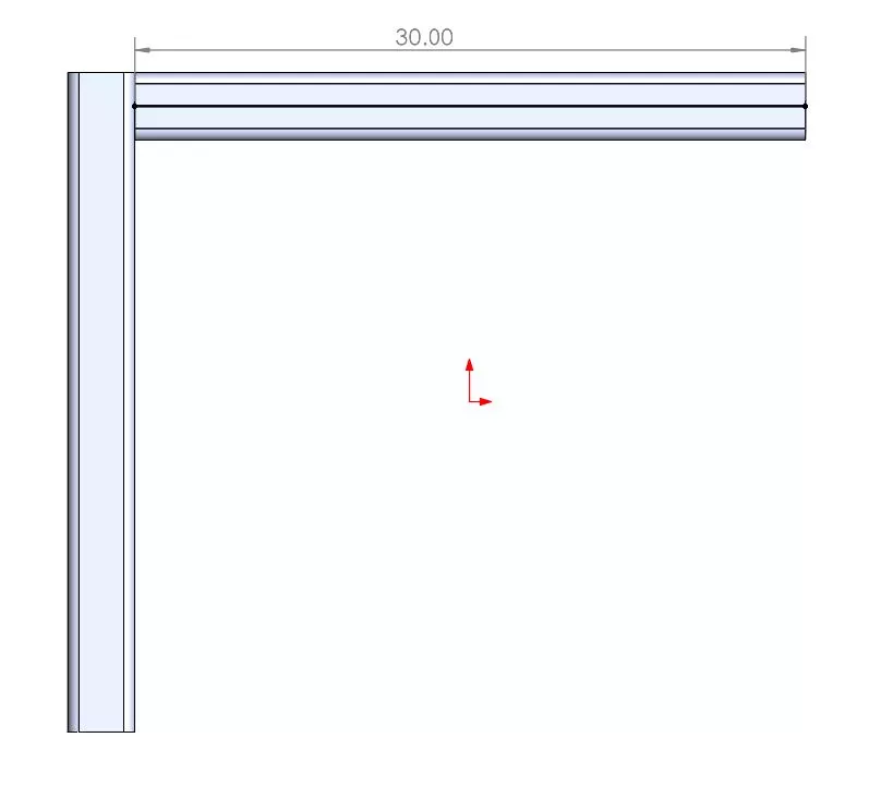
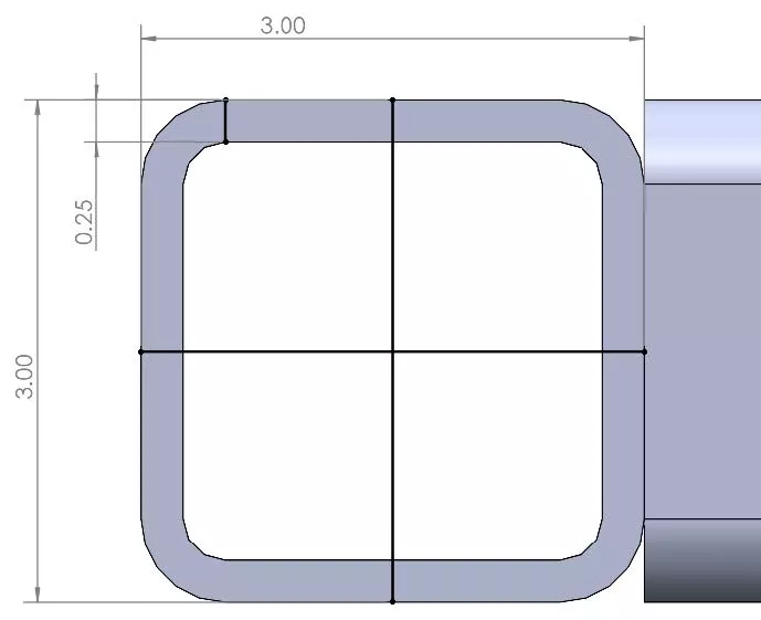
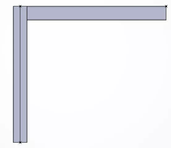
To follow along, simply create a set of two beams in SOLIDWORKS. They use 3” square profiles and are each 30” long. The beams are situated perpendicular to each other. (See the pictures below for dimensions.) They can be created in a multibody part file or SOLIDWORKS Assembly. In this case, this was made in a SOLIDWORKS Assembly.
Step 1 – Creating beam sections and profiles
In order to create Beam Sections in 3DEXPERIENCE, we must have Lines created in the Platform. Below are the steps to create line segments.
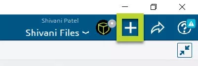
Import the beams from SOLIDWORKS into the 3DEXPERIENCE Platform. This is done using the plus sign, then Import options.
Note: This breaks the connection to the SOLIDWORKS file and will not import SOLIDWORKS sketches. Using the SOLIDWORKS Connector to import the SOLIDWORKS file will allow you to import SOLIDWORKS sketches, and thus, allow you to skip most of this step.
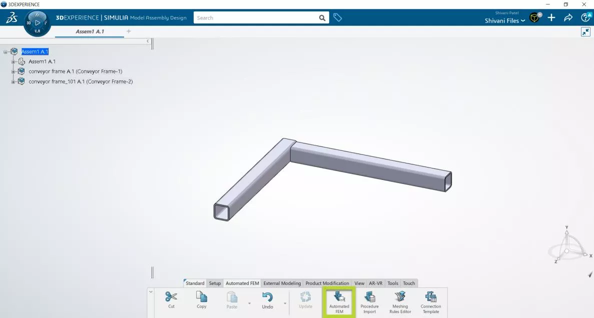
The model will look like the image below.
In the tree on the left-hand side, we see Assem1 as the bucket containing both parts and then two conveyor frame buckets representing each beam. From the Command bar, select Automated FEM and then Empty FEM.
Get back to the FeatureManager Design Tree and double-click on Assem1, or right-click on Assem1, go to object and select Edit.
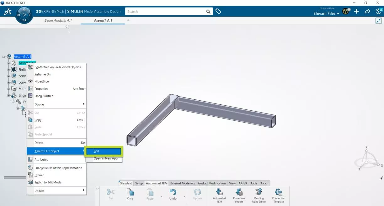
This reveals a geometry editing toolset. Go to the Create tab, and note the reference point and line options. In my opinion, the most efficient way to create the geometry we need is with the On curve and Between options for Reference Point and Point-Point for Line segments.
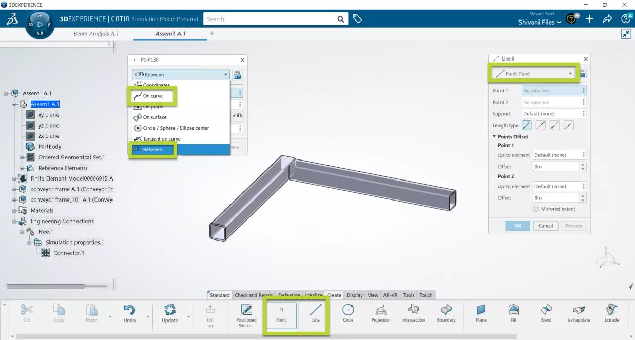
Starting with On Curve for Point, select a horizontal edge of one end of a beam.
Set Ratio to 0.5. This generates a midpoint.
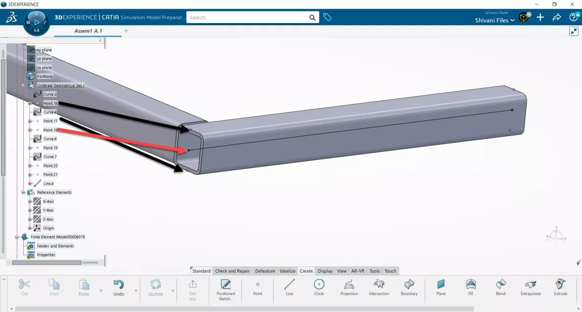
Repeat for the opposite side of the beam. Then, generate a third point using the Between option. Select the generated points (either by selecting them or, as is my preference, selecting them from the Ordered Geometrical Set.1 folder in the tree).
Ultimately, this will result in a point in the center of your beam.
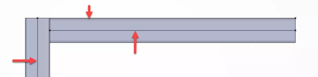
Repeat for the opposite side of the beam. Then, using Line and the Point to Point option, select the two profile centroid points and a line will be generated between them, exactly like the above and below photos.
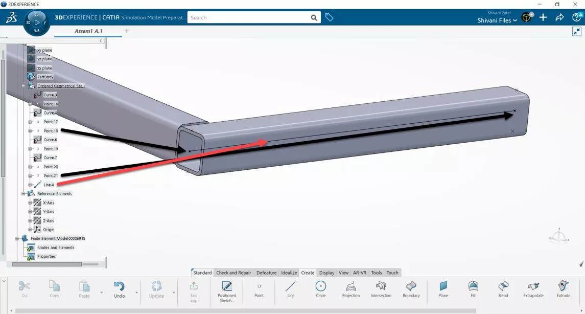
Now that we’ve created the segment for the first beam, should we repeat those exact same steps for the second beam? Not necessarily. I likely want the beams to align at the same vertex, so I can most easily represent the beams cleanly welded together.
This actually makes the point and line creation easier. We can reuse the Reference point already created and only need to create one extra Reference point, in this case, on the outer face of the second beam (see Point.22 in the below image).
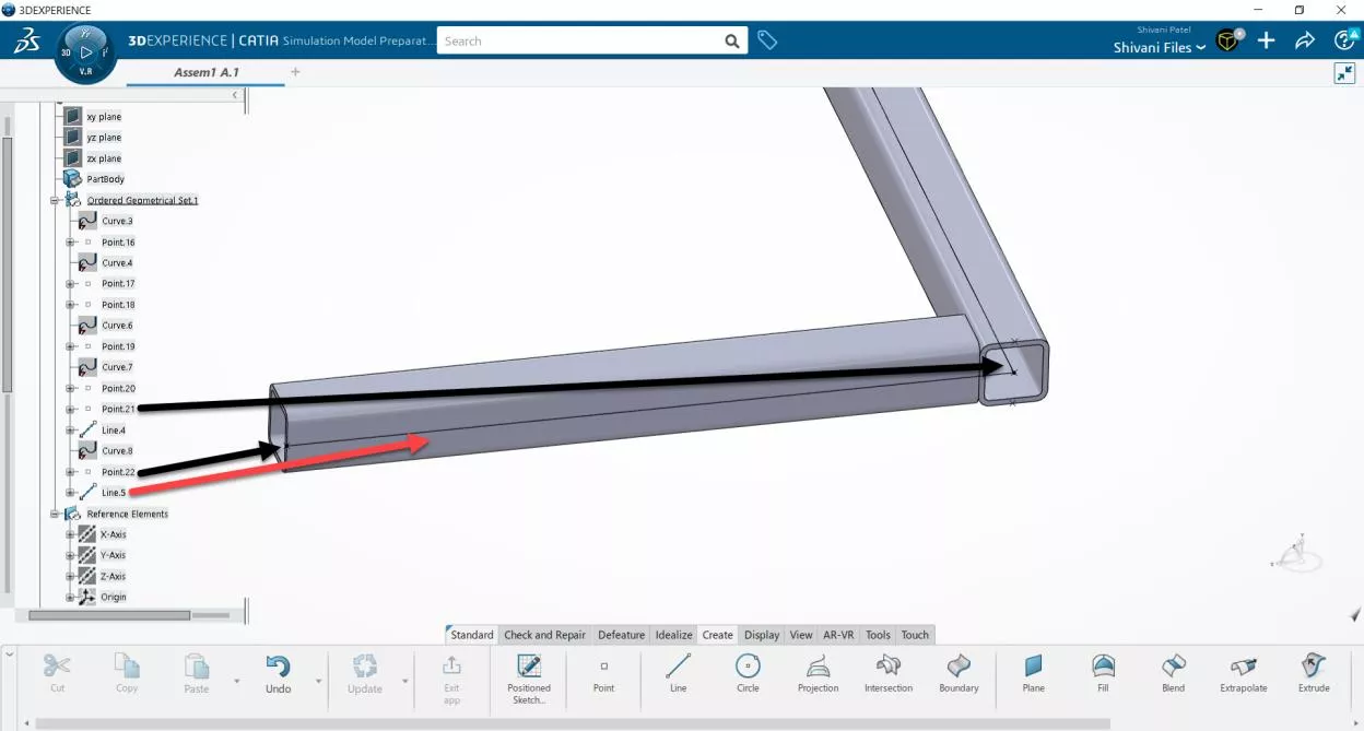
A line is then created between those two reference points. In the Top View, we can more clearly see that one line segment is through the centroid of Beam 1, and the second line segment is along the outer side of Beam 2.
For the purposes of training, I have created a third line segment along the centroid of Beam 2. You do not need to do this.
At this point, the only geometry that matters is the line segments. Reference points are useless to us now. Hide everything but the line segments that you will use as Beam Sections.
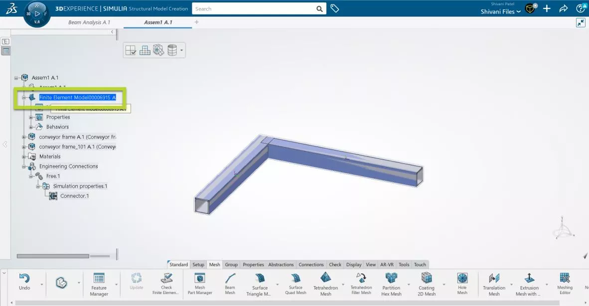
Double-click on your Finite Element Model to return to where we can create Beam Sections.
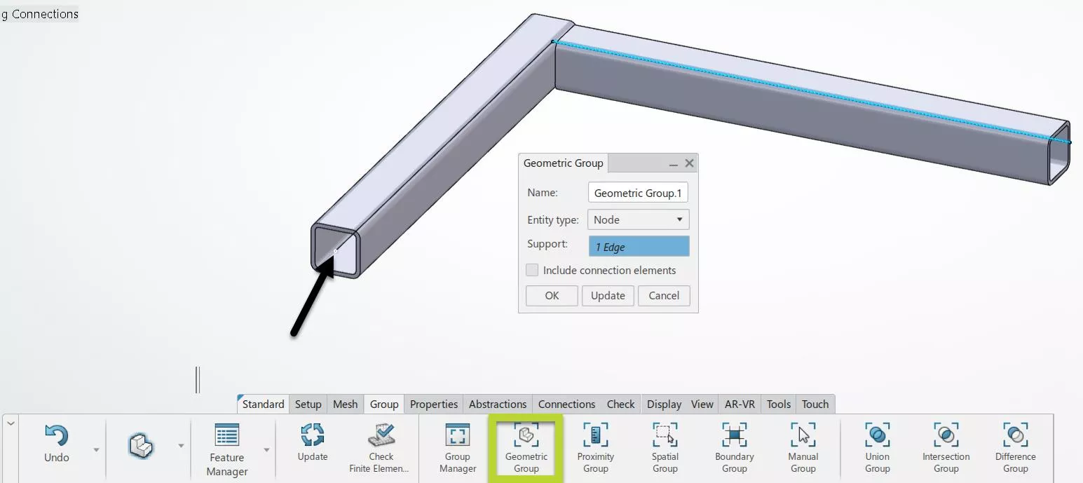
Tip: Go immediately to the Group tab and Geometric Group. Create groups where you select line segments or vertices that you plan to use for loads or restraints. This will make future setup much easier. If you are using a SOLIDWORKS Sketch, you’ll need to do this after meshing the line segments.
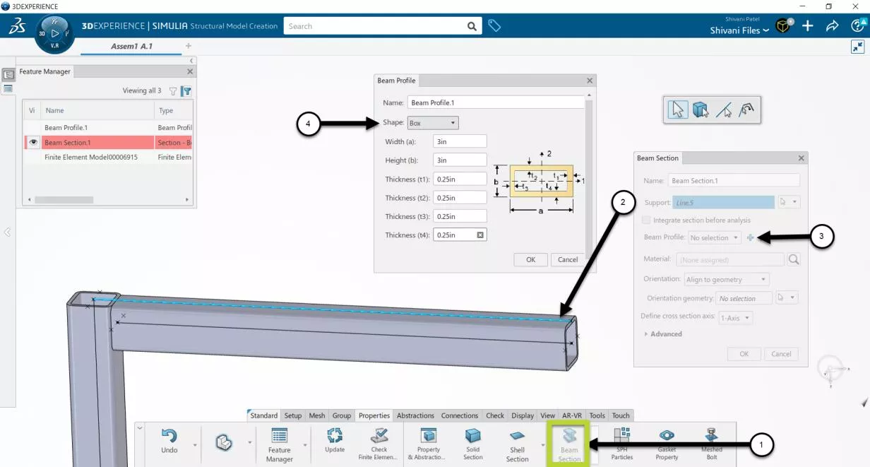
Switch to the Properties tab and select Beam Sections. For Support, select one of the line segments. For Beam Profile, select the Plus sign. A Beam Profile dialog box appears. For Shape, select the polygon that best represents your beam. In this case, Box is closest and I will put in the dimensions I used in SOLIDWORKS.
Once we’ve selected OK on Beam Profile, Beam Section becomes active again.
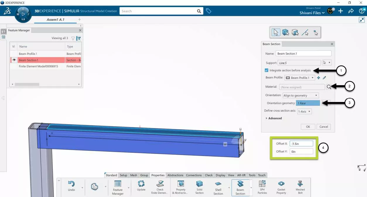
Hit the checkbox for Integrate section before analysis. This option allows you to translate the location of the profile about the line segment. If this remains unselected, the line segment is assumed to be the centroid of the beam.
Select a default material. In this example, I used AISI 1020.
For orientation, I used the default Align to Geometry and selected one of the structural member faces to orient the profile. If this is not what you want, switching Orientation to Rotate allows you to set a degree of rotation about the line segment.
Note the Offset dialog box highlighted below. This dialog only appears if Integrate section before analysis has been selected. This box will sometimes appear behind the Beam Section pop-up window, so if you do not see it on your screen, try moving the pop-up windows.
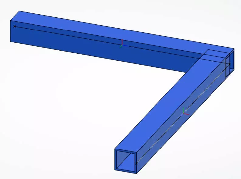
Note that the beam section is clearly interfering with what will eventually be the other beam. This is normal for beam analysis.
Repeat these steps for the other beam.
At that point, I will typically hide the original structural beams because they are no longer useful. This results in the below image.
Step 2 – Creating Beam Joints
The next step is to tell the software that these two beams are normally welded together. How does that translate in regards to Degrees of Freedom (DOF)? A perfect weld is where all the translations and rotations transfer from one beam to another.
What about a truss? All translations transfer, but none of the rotations. Said another way, the beams can rotate independently of each other.
The picks and clicks demonstrated next will be a manual method to create and customize beam joints. Dropdown options are available allowing you to define which degrees of freedom are transferred between the segments.
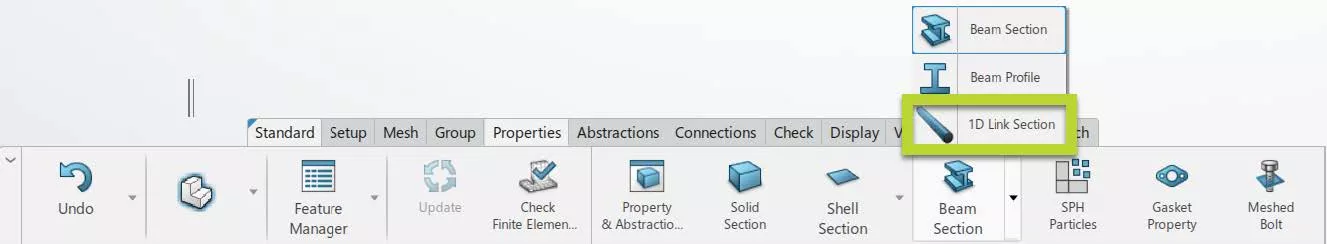
Note: Prefer to use the automatic method? If you’ve imported a SOLIDWORKS Sketch, lines with shared vertices will, by assumption, be connected. Second, the 1D Link Connection is a truss element.
Manual method
Go to the Connections tab and select Connector. Leave this on Default.
Hover over the vertex at the end of the line segments. Hold down the ALT key on your keyboard, then hover over the vertex. The vertex will highlight.
It is typically a black dot, and it will highlight into a white dot. Select the vertex. You will get a SelectionManager pop-up showing everything selectable at that point.
If performed correctly, you will now see Vertex options (boxed in green below).
If you see options starting with Point - BEWARE!. This means you did not hide your reference points. Do not select the reference points, as this will cause the Connector to fail.
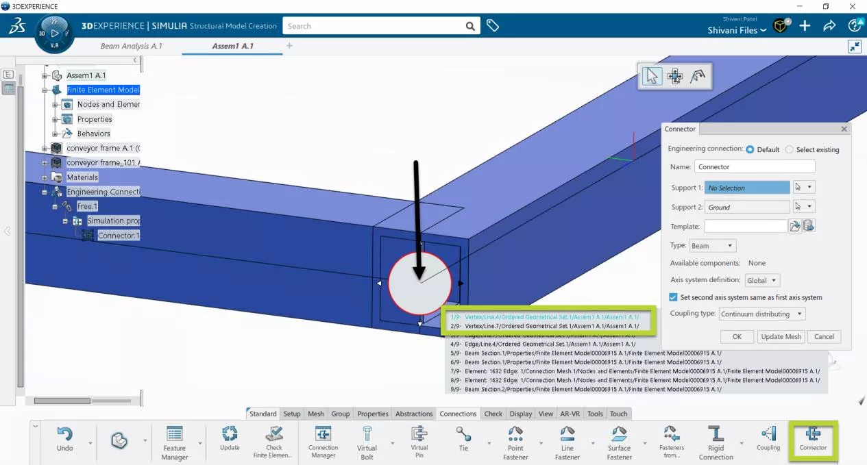
For Support 1, select the vertex of one of the lines. For Support 2, select the vertex of the other line.
With the time this took, we’re starting to see the benefit of pre-creating Geometric Groups, so these picks and clicks don’t have to be repeated.
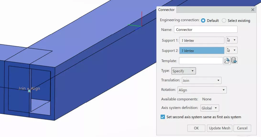
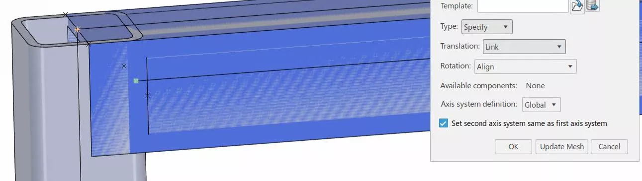
Change Type to Specify. This gives us individual choices for Translation and Rotation.
For Translation, select Join. This transfers all three translational degrees of freedom.
For Rotation, select Align. This transfers all three rotational degrees of freedom.
In this way, we have fully connected the two beam segments so that they act as one solid. How would we represent a Truss? In the Rotation’s dropdown, there is an option for None. Thus, no rotations are transferred. There are many options in the dropdown, which can be confusing for first-time users. The help menu is your friend. Here is quick access to the About Connectors help article.
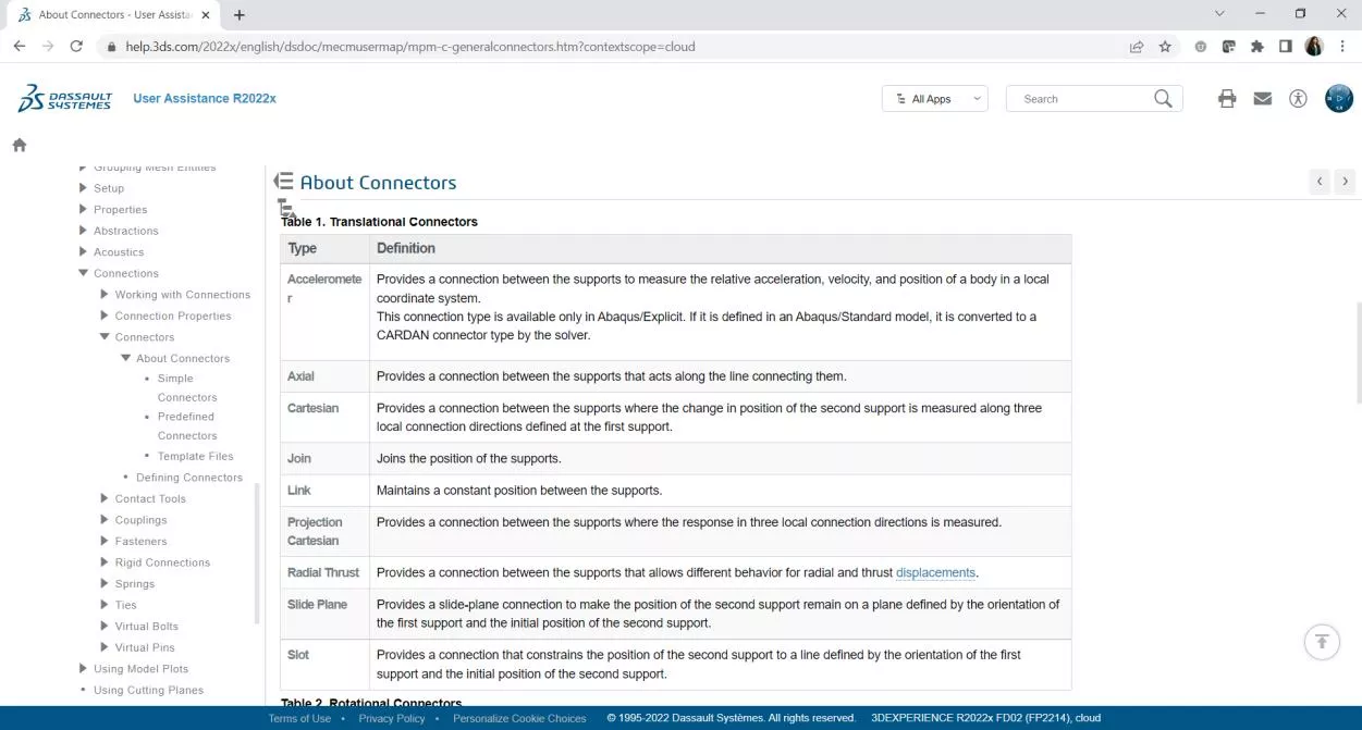
What if my beam vertices do not connect? Really, the connection type is up to you.
I recommend Link, which “maintains a constant position between the two points”.
Step 3 – Creating Beam Mesh
Beam Mesh chops up the 1D line element into smaller sections. How do I set the size of those smaller sections? Does a linear or quadratic polynomial represent how the line segment can bend?
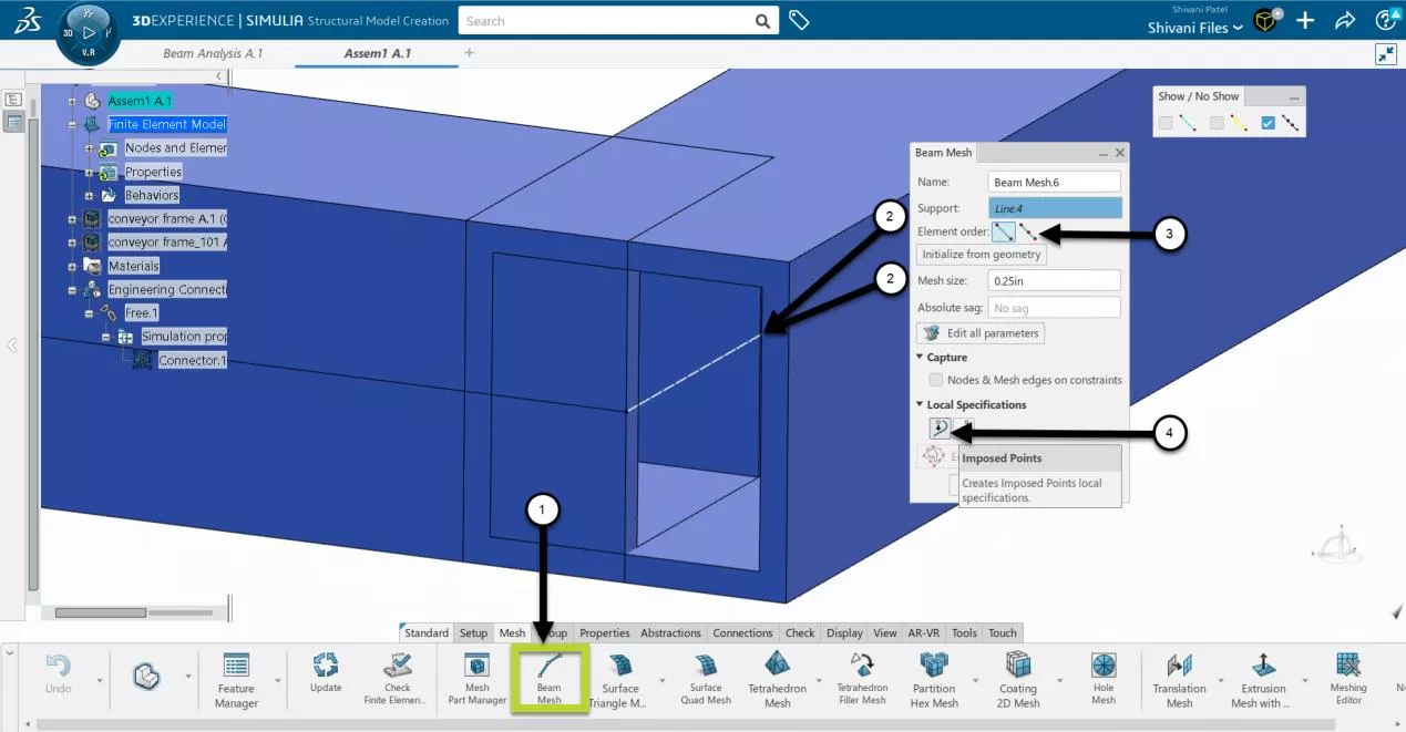
Go to the Mesh tab and select Beam Mesh.
For Support, select a line segment, and for Mesh size, type in a width. In the picture below, white dashed lines represent the 0.25in sections chosen.
Marked by a “3” is the Element order. The default option is linear, and the second option is quadratic. This represents the polynomial equation used when determining how the line section bends.
What if there were other beams joining at other points along this beam? It is a good idea to make sure the mesh nodes align with the joints defined with those beams. To make sure the nodes align, under Local Specifications, hit the Imposed Points button, and select the vertices of the other joints.
Click Mesh and OK. Repeat for the 2nd beam.
Your model will not look very different, but in the Finite Element Model bucket of your tree, in Nodes and Elements, you will see two items for Beam Mesh.
Note: If you are using SOLIDWORKS Sketches, you will need to make your Geometric Groups using these Beam Meshes and their nodes, rather than the sketch lines and vertices. This completes everything we would do as part of the FEM-Rep for the beam analysis.
Step 4 – Applying Loads and Restraints
From your Compass, activate the scenario creation you have access to. Again, Structural Designer roles cannot use this FEM-Rep. For the images below, I’ve used the top-level SME role.
In this example, we’ll perform a simple setup. We will fully constrain the free ends of the beams as if they were connected to a much stiffer structure. We will apply a gravity load and a force load on one of the beams.
Under the Procedures tab, create a Static step with an initial increment of 0.1s.
Under the Boundary Conditions tab, choose Fixed Displacement. You may need to hit the arrow next to Applied Translation to access Fixed Displacement.
For Support select the vertex of the line segment or the node of the beam mesh. Again, if you select a Point, the fixture will fail.
Set Translation and Rotation DOFs as you prefer. In this case, I have fully fixed the point in space.
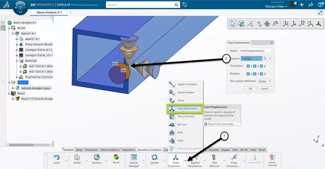
You can then select the vertex of the other beam in the same dialog box. In this case, I created a separate Fixed Displacement fixture for the second vertex.
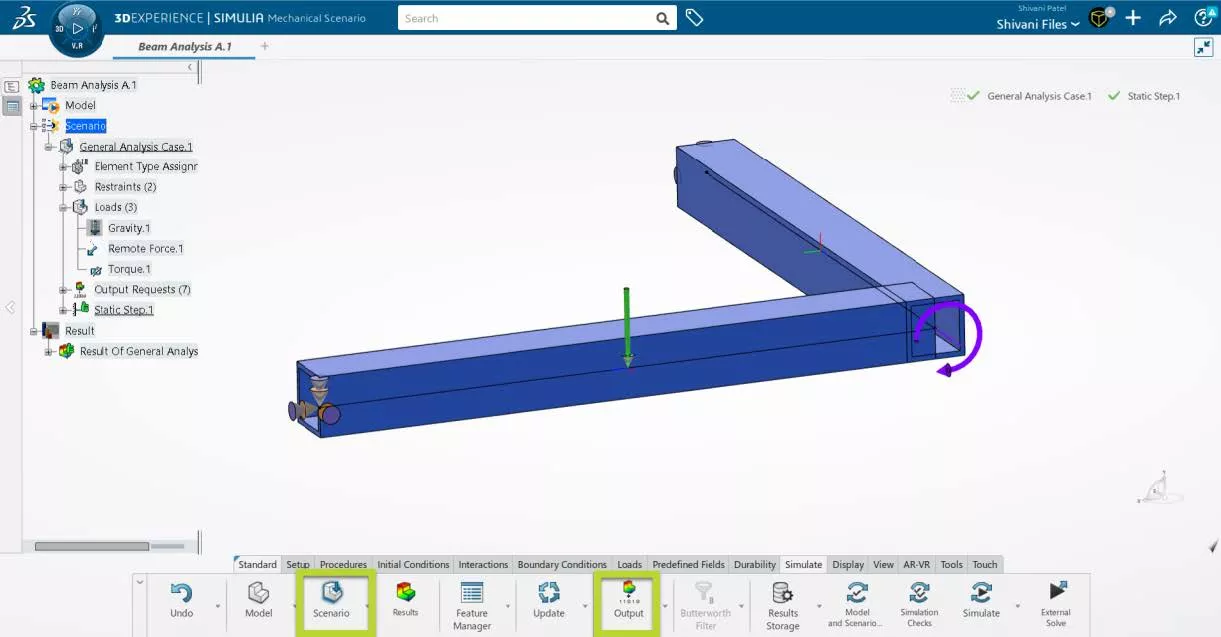
Go to the Loads tab and select Gravity.
Whole Model is chosen by default. This is perfect, and nothing needs to change. Set gravity in the negative Y direction.
For Loads, let’s discuss how to apply a load at any point on the beam and how to apply a Force or Torque at a joint.
How to apply a Force or Torque at a joint (the vertex connecting two beams)
This is the same as applying any Fixed Displacement.
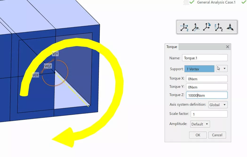
Go to Force or Torque options. If your selection filter pops up, select the Point filter. Otherwise, select the vertex at the end of the line segment. This applies the force or torque at that vertex. You can also individually select mesh nodes or a random point along the beam.
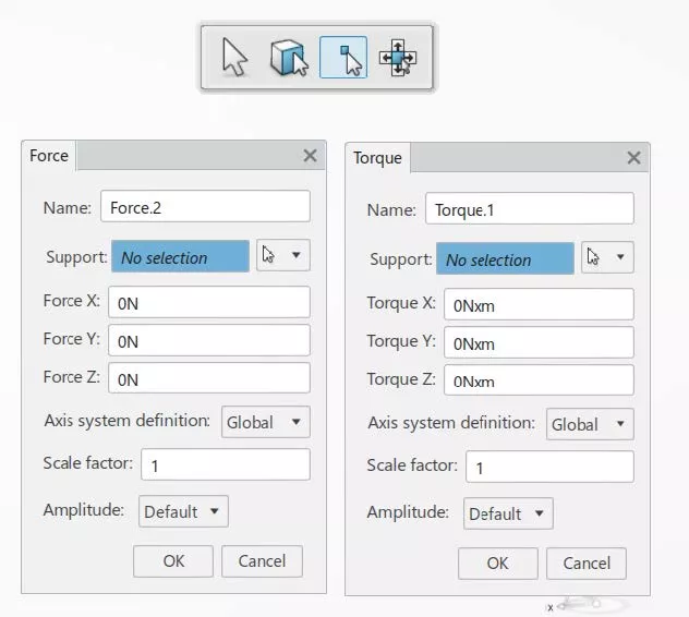
In this example, I’ve applied a 10,000 Nm Torque load about the Z-axis.
How to apply a load somewhere on the beam without creating a vertex or selecting a mesh node
Remember, a reference point isn’t going to work here. The easiest method is through Remote Load.
Hit the dropdown arrow next to Force to select Remote Force from the menu.
For Support, select one of the line segments.
By default, Reference point input mode is set to Specify, and Axis system definition is set to Global. The force will apply at the centroid of the line segment. It is applying at a single point on that beam.
Note the dialog box with Global X, Y, and Z coordinates. This is the point of load application, and we can shift that as desired.
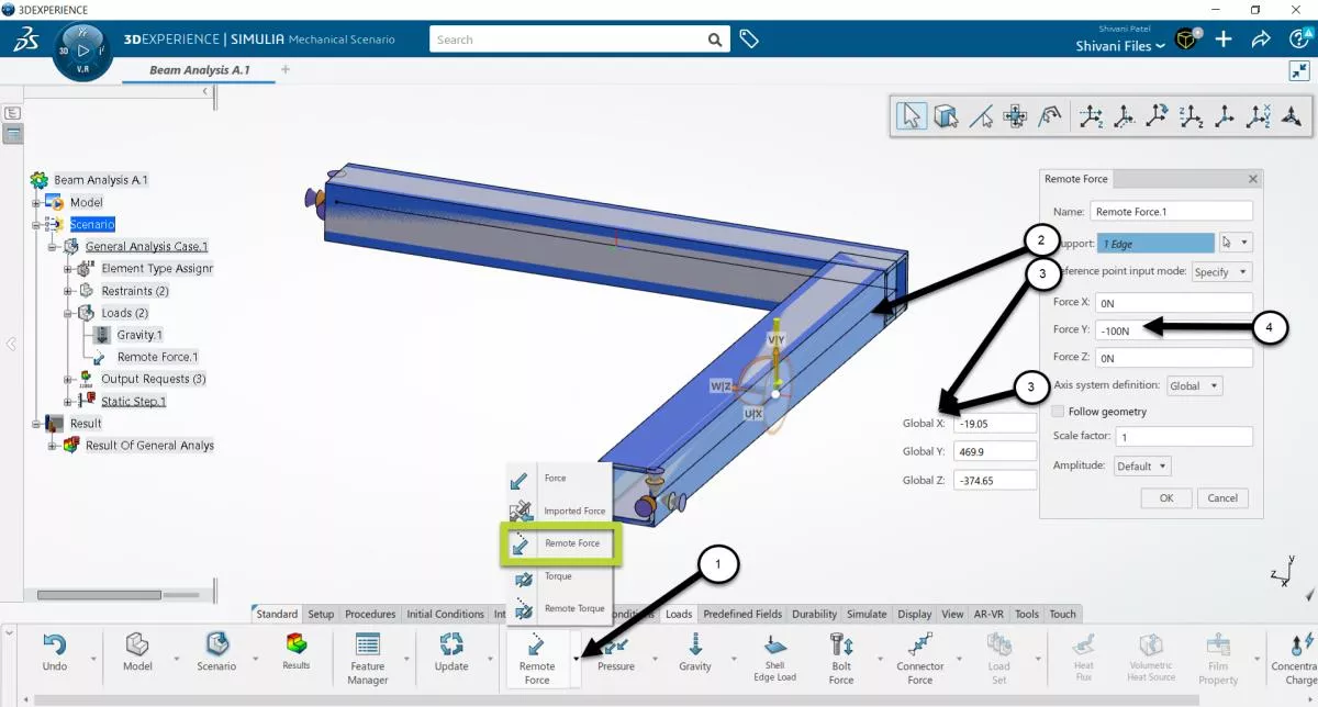
In this example, a force of 100,000N was applied in the negative Y-direction.
From there, go to the Simulate tab and run the beam analysis.
Step 5 – Navigating the Results
What is the maximum displacement or stress in the structure?
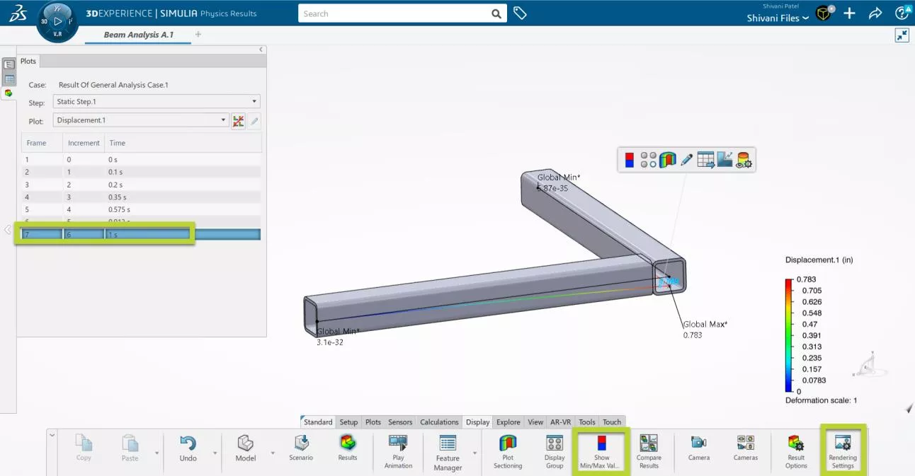
The time segments range from 0 to 1s, where 1s is where the total load occurred. Clicking through the time segments showed us how the beams bent over time.
To overlay the original position of the beams like in the picture below, go to the Display tab > Rendering Settings, and hit the checkbox for Show Model Geometry.
To view the minimum and maximum values on the graph, go to the Display tab and select Show Min/Max Values.
Finally, you can hover over any section of the beam element and get a callout of displacement or stress, etc.
Now let’s focus on four key numerical outputs.
- Reaction Forces/Moments at the fixed vertex
- Forces / Moments at the Joint
- Total Forces / Moments through the beam
- Forces / Moments for each mesh segment of the individual beam element
For each of these, we must create special Outputs before running the analysis. To follow along, go back to the Scenario app, and the Simulate tab. Click Output. For each Output, we will use History instead of Field. History is a numerical plot output, Field is a colored contour plot.
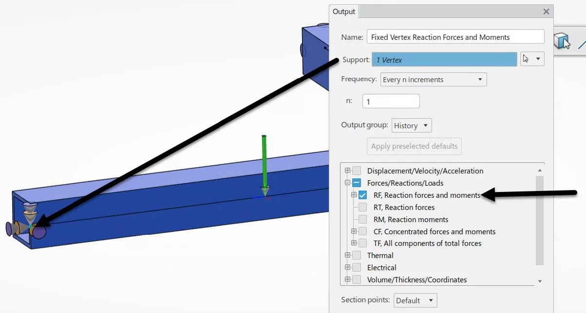
Reaction Forces/Moments at a fixed vertex
In the Output dialog, hover over one of the vertices where Fixed Displacement is applied. Under Forces, select RF - Reaction Forces and Moments.
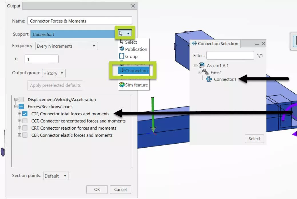
Forces/Moments at the Joint
Hit the dropdown arrow next to support and choose Connections. From the list, choose the joint you wish results for.
Under Forces, select CTF - Connector Total forces and moments.
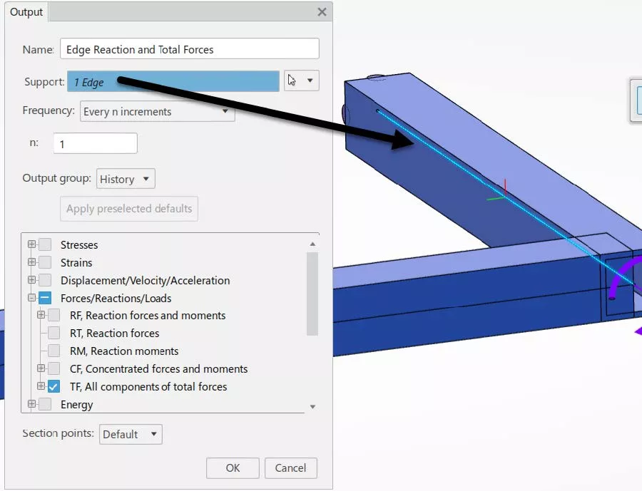
Total Forces/Moments through the beam
Select the line segment used to create the Beam Sections.
Under Forces, select TF – All components of total forces.
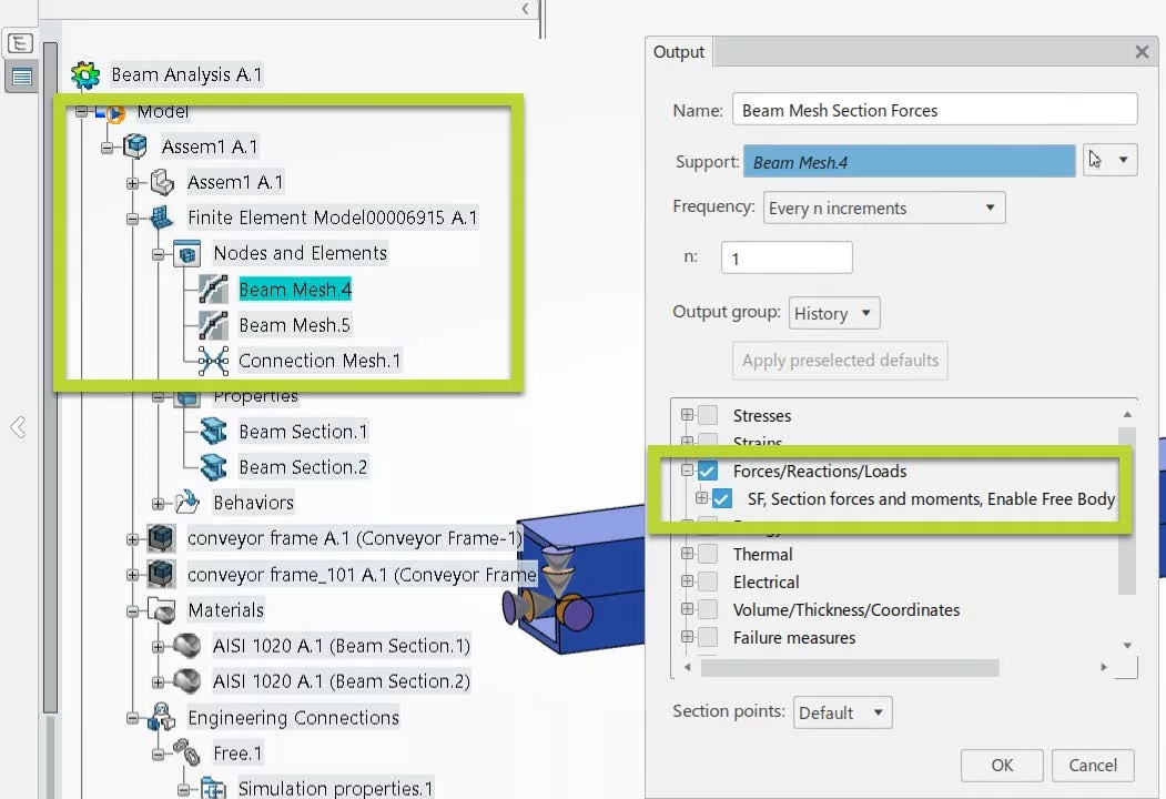
Forces / Moments for each mesh segment of the individual beam element
Go to the flyout tree and navigate into the Model dropdown > Assembly name dropdown > FEM-Rep dropdown > Nodes and Elements. Here are the Beam meshes for each beam. Select one to extract results for.
Under Forces, select the only option SF – Section forces and moments.
Keep notes of the letters used to represent the results you chose, like “SF” in the last example.
After re-rerunning the Simulation, plotting these results is done with the same series of clicks.
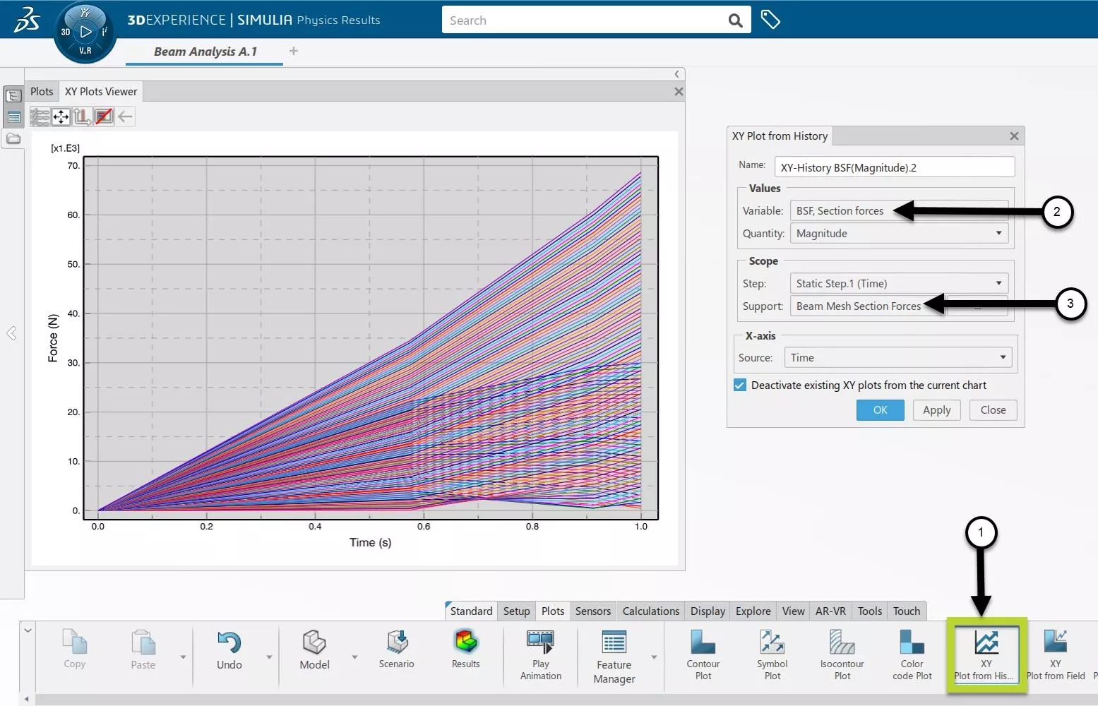
In the Plot tab, select X-Y Plot from History. Under Variable, navigate to the result you want to plot. This is why keeping note of the abbreviations for the results we chose can come in handy. In this example, “RF”, “CTF”, “TF”, and “SF” were used.
In the XY plots, that equations to “RF” = Reaction Forces, “CTF” = Connector Total Forces, “TF” Total Forces, and “BSF” Beam section forces. Below is a plot of Beam Section Forces.
Support, pointed to by Arrow 3 in the picture below, refers to the Outputs we generated. I’ve given them sensible names, which is why we see Beam Mesh Section Forces here. We can toggle between various valid Outputs by hitting that dropdown.
Any of these plots can be exported as a .csv or Excel file for further data manipulation.
Conclusion
This tutorial has covered how to build a FEM-Rep that converts structural members into Beam elements, how to apply forces and torques at any point on the beams, and how to extract common forces, moments, displacements, and stresses.
Whether done in SOLIDWORKS or the 3DEXPERIENCE Platform, setting up the sketch geometry to become Beam Segments can be time-consuming, but we benefit from the manual control so joints and profiles are exactly where we want them.
Beam analysis just touches the surface of the efficiency methods the 3DEXPERIENCE SIMULATION portfolio provides to SOLIDWORKS and Platform users. To learn more, check out other articles and YouTube videos from GoEngineer, or reach out to us at goengineer.com. We’re here to help.
Related Articles
3DEXPERIENCE Platform 2022x FD02 Release: Top Enhancements
What’s New SOLIDWORKS 2022: 3DEXPERIENCE
Getting Started with 3DEXPERIENCE: Setup, Dashboards, Connectors & More

About Shivani Patel
Shivani has a background in aerospace engineering, and is the Engineering Manager for southern Texas. She has the Elite certification in SOLIDWORKS and is happy to jump into anything in the SOLIDWORKS licenses. Her main specialty is Simulation - and has spent the past 6 years digging into the Motion Analysis, FEA and CFD programs and supporting many of our oil and gas customers in the south.
Get our wide array of technical resources delivered right to your inbox.
Unsubscribe at any time.