5 CATIA V5 Modeling Tips for New Users
There are various techniques in CATIA V5 for modeling. While there are multiple ways to achieve most model features, some methods are more efficient and stable than others. Here are my top 5 favorite tips I have picked up in my 30 years of experience using CATIA.
#1. Dimension sketches to axis systems, planes, or other sketches
Dimensioning sketches to faces (or worse, tangent lines of radii or hard edges) can sometimes create update errors or undesired geometry when reference geometry parameters are edited.
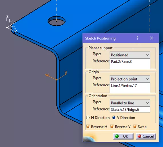
#2. Ensure sketches are oriented properly
When creating a new sketch, the H Direction and V Direction will typically align to be square to the part of the active axis system. If the sketch axis is not aligned, use the Positioned Sketch function to align the Origin and Orientation of H and V to the features being created. This can take a bit more time to set up, but if the sketch axis is off, the automatic H and V of the sketch constraint dimensions will not align with the intent of the design.

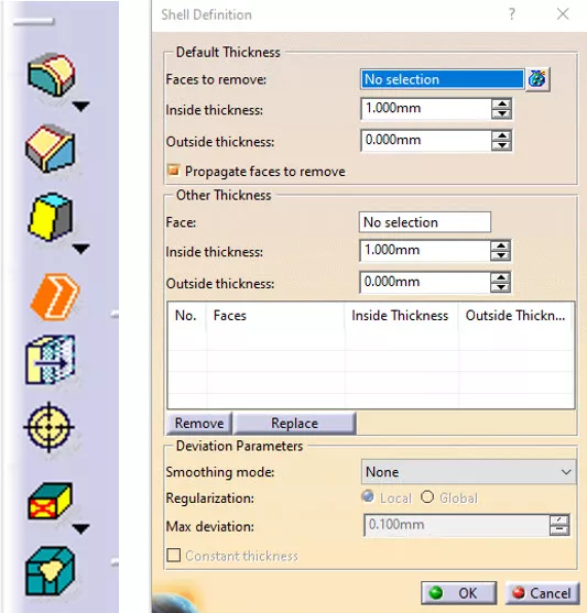
#3. Use the Shell command for stamped components
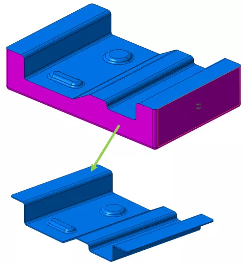
While the Sheet Metal Design module is popular for simple press-brake style stampings, it doesn’t always work for complex stampings. During part design, both basic and complicated stampings can be created and managed using the Shell command. The upper or lower part of the desired final stamping die is solid modeled, then the Shell command is used to result in the desired stamped part. This allows for more complex organic shapes, variable radii, and custom or irregular beads.
The basic sample shown only requires three sketches and a few radii to result in the stamped shell.
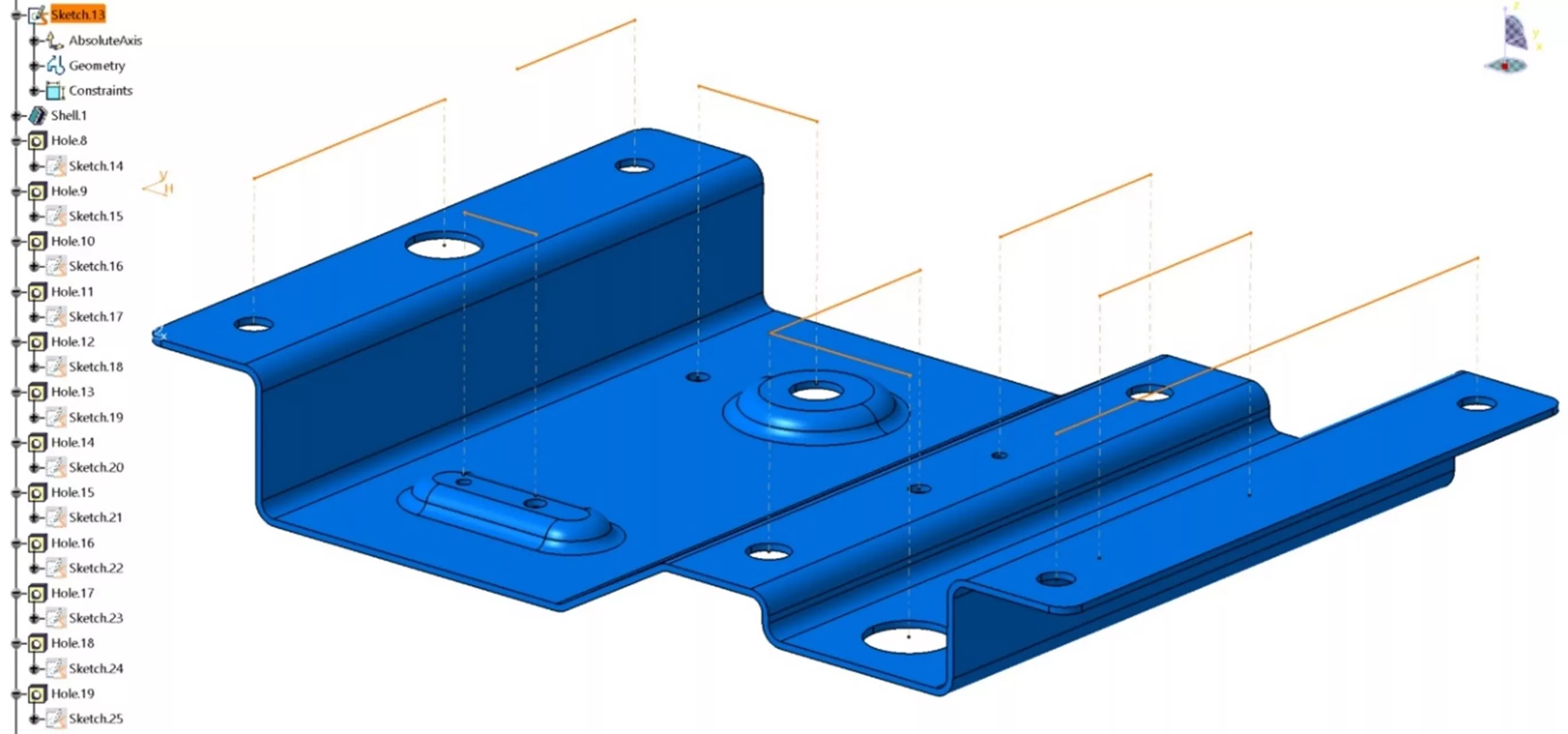
#4. Use sketches for coplanar holes
The Pattern function can be used to achieve hole patterns in parts. While this works with a single-size hole or feature, optionally, lay out all of the coplanar holes within a single sketch regardless of their individual specification. This sketch can then be used to create the mating holes in other CATParts via paste with link. When editing the sketch, all the holes will update to the new locations.
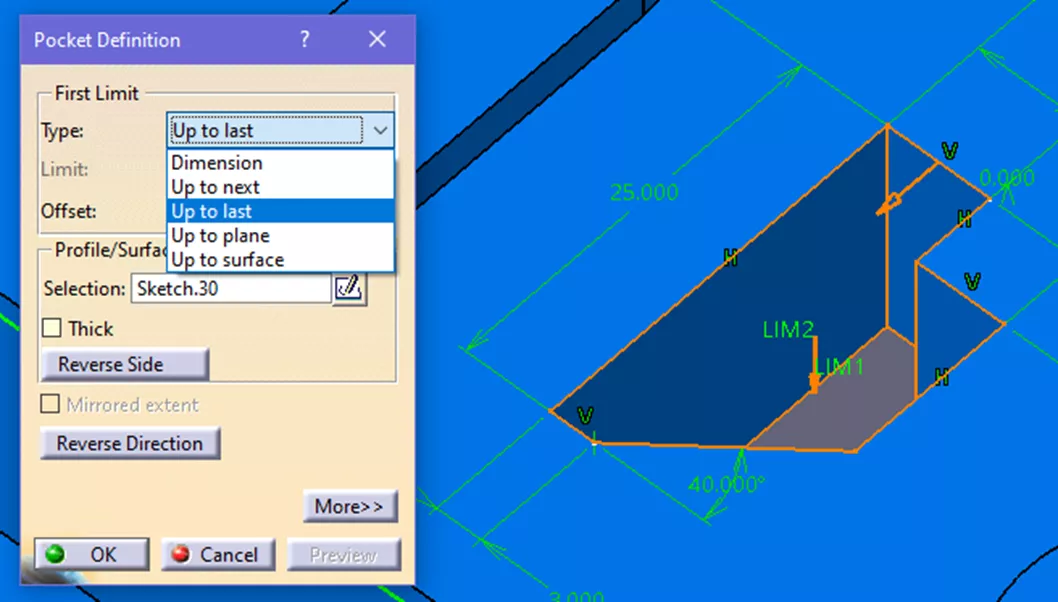
#5. Use "Up to last" or "Up to next" when modeling
When adding or subtracting geometry from a part body, these options can help keep the parametric nature of the model intact. However, they should only be used when a feature goes all the way through or up to the extent of a part. However, if a specific feature depth is required, such as a 5mm pocket, use the Dimension option.
CATIA V5 Training
I hope you found these 5 CATIA V5 modeling tips helpful. Want to take your CATIA skills to the next level? Enroll in the official CATIA Fundamentals training course.

Check out more CATIA tips and tricks listed below. Additionally, join the GoEngineer Community to participate in the conversation, create forum posts, and answer questions from other CATIA V5 users.
More CATIA V5 Tutorials
Composites in 3DEXPERIENCE CATIA Overview
CATIA V5 Parametric Optimization Guide
6 Design Struggles in SOLIDWORKS that are Easier in CATIA
CATIA V5 Parametric Optimization Guide
![]()
About Cory Ostrow
Cory Ostrow is a Sr. Simulation Specialist at GoEngineer.
Get our wide array of technical resources delivered right to your inbox.
Unsubscribe at any time.