Easing the SOLIDWORKS to CATIA V5 Transition
Many people assume that transitioning from SOLIDWORKS to CATIA V5 will be easy since both are developed by Dassault Systèmes. However, this is not the case and users quickly realize the differences, leading to frustration in the process. Over the years, we've heard common pain points that these users have expressed. In this article, we cover the CATIA V5 interface, sketching, solid part design, and assembly design.
CATIA's Additional Design Tree Node: Parts vs 3DShapes
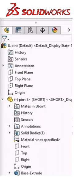
First, let's examine the differences in Design Tree. Both SOLIDWORKS and CATIA have assembly, sub-assembly, and part levels. However, they differ in the location at which geometry and part features can be built.
In SOLIDWORKS, features are accessed at the part level, whereas with CATIA, one must expand an additional node in the tree to access geometry and part features. This extra node, known as the 3DShape, must be activated in order to actually build geometry.
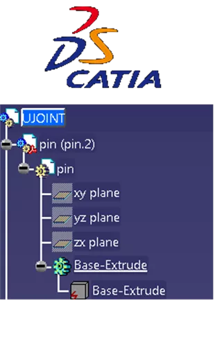
In CATIA, the part level is used to contain metadata associated with a part, such as the Part Number (or Title/Name), and is used to populate the Bill of Materials (BOM). Since the Part Number and part features are housed in different areas, this makes it easier to swap to another geometry variation without changing the Part Number in the Bill of Materials. Using Manage Representations we can change which 3DShape is associated with the part without modifying how the BOM reads the part.

Workbenches and Toolbars
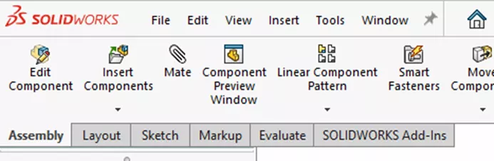
If an assembly is open in SOLIDWORKS, we can observe that our assembly features are in a toolbar at the top of the interface with subsequent features stored in tabs. To edit a part, highlight the part and select Edit Component; this will give you access to your part design features.
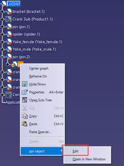
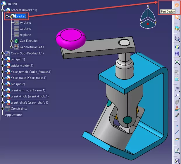
CATIA works a bit differently in this regard. First, the commands are located around the perimeter of the interface and are placed categorically into toolbars. To edit a geometry and access your part-based features, activate the 3DShape by double-clicking it or using right-click > [3DShape name] object > Edit.
You will now notice that you have switched workbenches, and your toolbars all contain part design features. By default, in the top-right interface, is a Workbench toolbar. Hovering over this icon will reveal the current workbench.
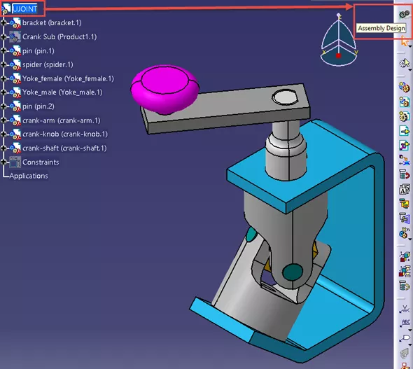
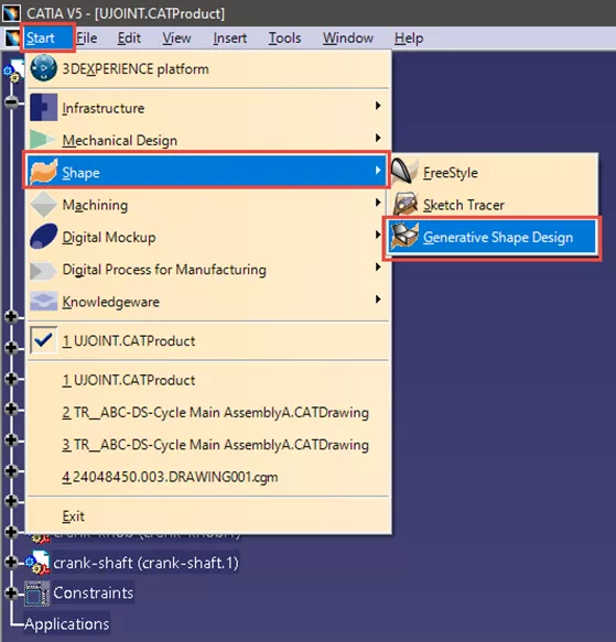
CATIA has multiple workbenches for each context. For example, in an assembly context, you can use Assembly Design or Product Structure Design. For Drawings, you can use Drafting or Functional Tolerancing and Annotation. For Parts, you can use Part Design or Generative Shape Design (to name a few). To switch workbenches within the same context, navigate to the Start dropdown in the top banner. In the example of switching from Part Design to Generative Shape Design, activate the 3DShape, then navigate to Start > Shape > Generative Shape Design.
Within any workbench is the option to move toolbars. Each toolbar is separated by a grey bar. Grabbing and dragging the grey bar will allow you to move that toolbar to another perimeter on your interface or anywhere in 3D space.
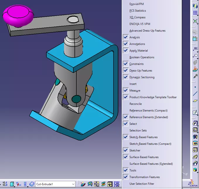
Also in CATIA, is the ability to toggle toolbar visibility. Right-click on any grey space in the perimeter to reveal a list of every toolbar available in your current workbench. Active toolbars are displayed with a checkmark. Clicking the toolbars in this menu will toggle their visibility.
If there is not enough space on the perimeters to display the toolbar, CATIA will “dock” them out of view. You know that a toolbar is out of view when there is a double chevron displayed at the corners of the grey perimeter. Moving the toolbars to a different location will reveal toolbars that are docked out of view. You can repeat this process until the double chevron disappears. Once the double chevron is gone, you know that all active toolbars are now visible.
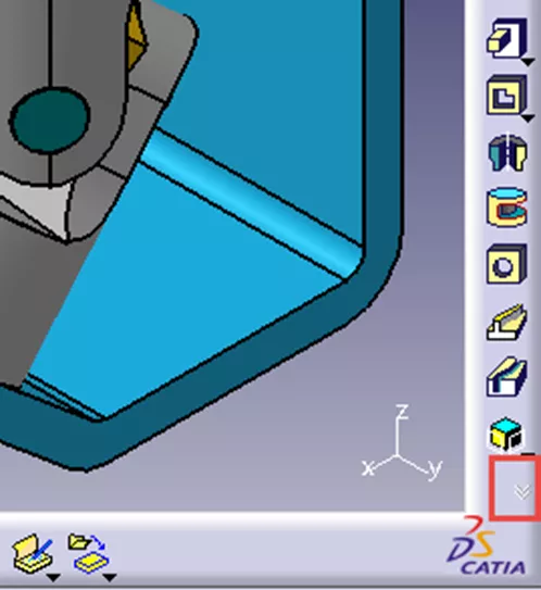
A toolbar is out of view if there is a double chevron displayed at the corners of the grey perimeter. Moving the toolbars to a different location will reveal toolbars that are docked out of view. You can repeat this process until the double chevron disappears. All active toolbars are visible once the double chevron is gone.
Status Bar
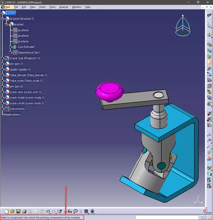
CATIA provides a handy feature known as the Status Bar, a string of text located at the bottom left of the interface. The purpose of the Status Bar is to inform you what CATIA is expecting you to do next. For example, if you want to insert an existing component into an assembly, you would navigate to Insert > Existing Component. However, when doing so, you may notice that your cursor will briefly display a loading wheel and seemingly nothing happens after that. Checking the status bar, you will notice that it says “Select a component into which the existing component will be inserted”, meaning, you must select an assembly before continuing. After selecting an assembly, you are then given options to select which component you want to insert.
View Manipulation (Pan, Zoom, Rotate) Controls
The Pan, Zoom, and Rotate functions in SOLIDWORKS use the roller button on the mouse in conjunction with your keyboard as hotkeys to perform these functions. For example, holding the roller button alone rotates a part, the roller button + Shift enables zooming, and the roller button + Ctrl will pan the part.
CATIA works similarly in the sense that it utilizes the roller button to perform these functions. However, instead of using the keyboard, CATIA utilizes the right-click button of the mouse.
CATIA also allows users to pick a center in which to rotate and zoom about. Clicking the roller button on an area of a part will move that area to the center of the interface, making it the center of rotation and zoom. It is good practice to designate a center before zooming and rotating.
To zoom, hold down the roller button while clicking and releasing the right-click. Moving the mouse up and down will then zoom the part in and out, respectively.
To rotate, hold down both the roller button and the right-click. With both held down you can then rotate your part about the center that you defined earlier. To pan, hold down the roller button by itself and move the mouse to pan the part accordingly.
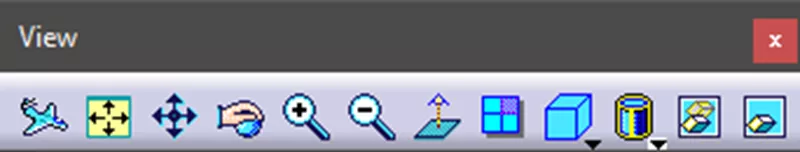
Similar to SOLIDWORKS, users have the option to select Pan, Zoom, and Rotate from a toolbar. In CATIA, this toolbar is the View toolbar and by default, is located at the bottom of the interface. In this toolbar, is the option to select Fit All In, Normal View, and to choose from global views (e.g., Isometric, Front, Back, etc.).
It should be noted that a SpaceMouse from 3DConnexion is fully compatible with CATIA and can be used as a standalone or in conjunction with the mouse-based features.
Finally, there is a feature at the top right of the 3D space known as the robot or compass (depending on the version of CATIA). This provides a few features. The first is that it will indicate where the base directions/planes are oriented about a part. If you rotate a part, you will notice that the robot rotates along with it. However, this feature can also be used to pan and rotate a part. Grabbing a line or plane on the robot will allow you to pan along a line or across a plane, respectively while grabbing an arc will allow you to rotate.
Tree Design Mode: An Easy Accidental Click
You may find yourself in a scenario where panning and zooming a part results in your tree being manipulated with your part having a shadow-like filter on it. This is called Tree Design Mode, which allows you to move and resize the design tree. Tree Design Mode is activated whenever any of the lines that connect the nodes within your tree are clicked. To exit Tree Design Mode, click on one of these node-connecting lines again. Users typically find themselves in this scenario when they are trying to expand or collapse a node and accidentally click one of these connecting lines.
Sketching in CATIA: Many Differences to Note
Just like SOLIDWORKS, CATIA provides a separate workbench for its sketching functionality and can be accessed by creating a new sketch or editing an existing one. Create a new sketch by selecting the Sketch or Positioned Sketch command from the Sketcher toolbar within the geometry design workbenches (Part Design, Generative Shape Design, etc.).
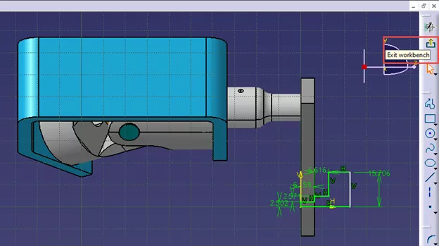
Optionally, when a 3DShape is active, navigate to Start > Mechanical Design > Sketcher and select the plane to make your sketch on. To edit an existing sketch, either double-click on the sketch in the tree or 3D. Alternatively, right-click on the sketch and select [Sketch name] object > Edit. Once within the Sketcher workbench, there is now an additional icon within the Workbench toolbar, and it is located below the icon that indicates you are in the Sketcher Workbench. This icon is also used to exit the Sketcher Workbench.
Dimensional and Geometric Constraints
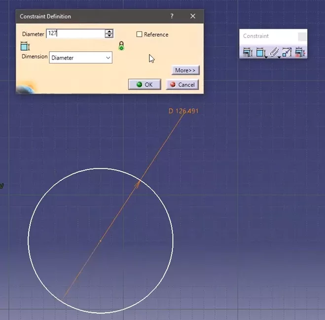
To dimension a sketch object in CATIA, navigate to the Constraint toolbar, select Constraint, choose the object to constrain, and then where to place the callout. Unlike SOLIDWORKS, the option to immediately edit the input value is unavailable. Instead, just double-click the constraint. The command window will appear to edit the value. Additionally, if you are constraining circular objects, this window is where you can toggle between Radius and Diameter.
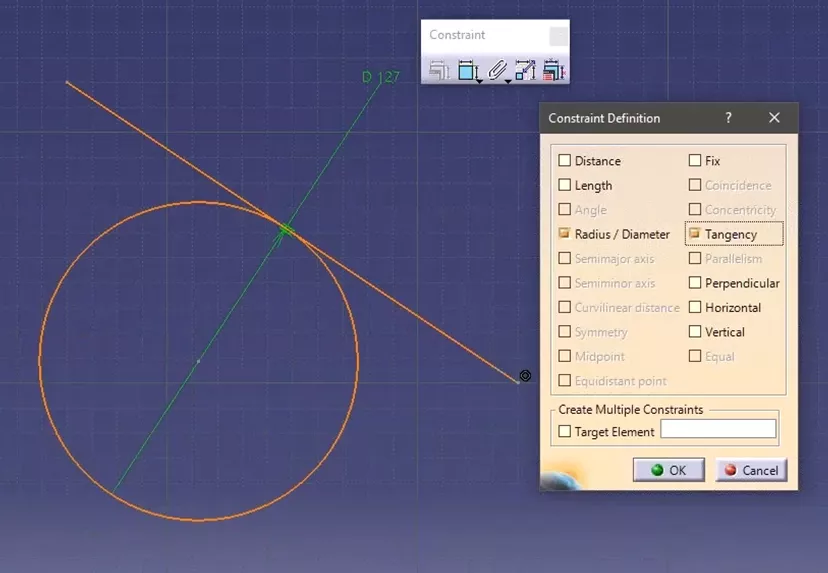
Geometric Constraints require the objects to be pre-selected before you can access any relevant commands. You can set Geometric Constraints on one or multiple objects, where multi-selection can be achieved by holding down the Ctrl key and picking multiple objects.
Once an object(s) is selected you can set a Geometric Constraint in one of two ways. Right-click > [object name] object and a list of relevant constraints will be shown. However, this list is limited, so the better option is to navigate to the Constraint toolbar and select the Constraints Defined in Dialog Box command. Here, you will be presented with a list of constraints. The constraints that are not applicable to your selection will be greyed out.
Toggling Snap to Point
The Snap to Point feature, in the Sketcher Workbench, is turned on by default. It tends to frustrate new users because it forces you to only pick and place geometry on the intersections of the grid. However, it is often required to place features in other areas - so we'll need to turn this feature off.
There are a few ways to do this.
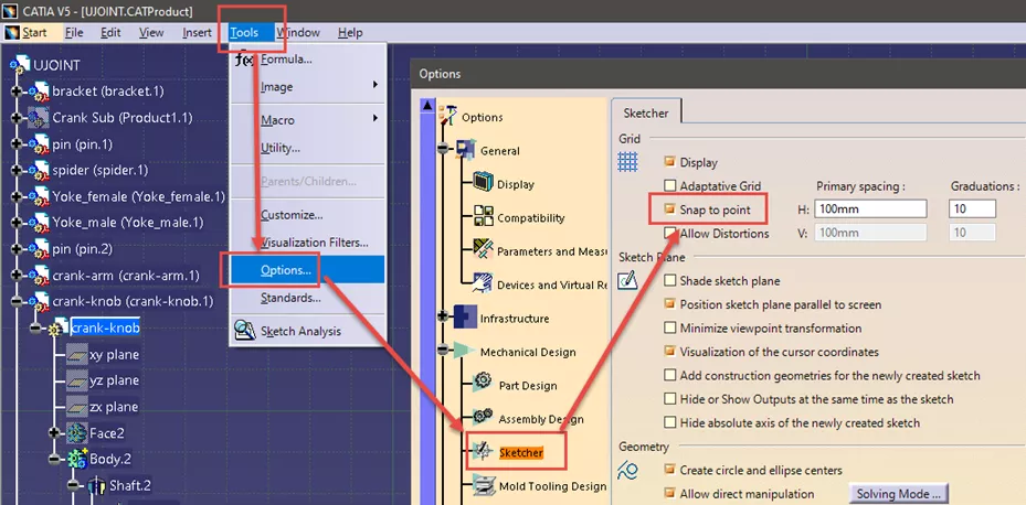
One option is to toggle the feature persistently by navigating to Tools > Options > Mechanical Design > Sketching > Grid and then toggle Snap to Point.
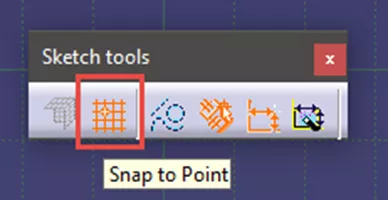
Another option is to toggle Snap to Point within the Sketch Tools toolbar in the Sketcher Workbench.
Finally, you can temporarily disable this feature by holding down the Shift key when attempting to place an object. The option to temporarily disable Snap to Point using Shift extends to any workbench that utilizes a grid, like the Drafting Workbench, for example.
Sketch Profile and Persisting Commands
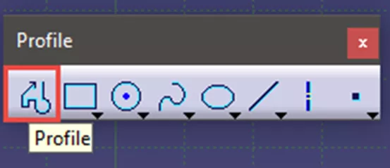
Within SOLIDWORKS Sketcher, the line command can also be used to create a profile. CATIA’s line feature will only allow you to create a single line and you must re-select the command to create another line. However, double-clicking will persist the command and keep you from having to re-select it every time. You can end the persistency by hitting the Esc key or selecting a new command. The option to persist by double-clicking extends to just about every command in every workbench. In CATIA, the “profile” functionality is accessed by selecting the Profile command, located within the same toolbar as the rest of the wireframe commands.
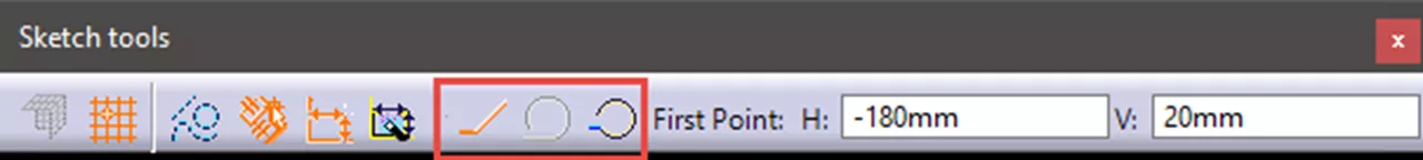
Once the Profile command is active, you can create the profile by selecting the end point of each segment. In SOLIDWORKS, if you wanted to toggle from a straight line to an arc, you would bring your cursor back to the last endpoint and the software would toggle to an arc feature for you. In CATIA, you must navigate to the Sketch Tools toolbar and select between Arc, Tangent Arc, or Line.
Multi-Pad and Multi-Profile Features
In the scenario where there are multiple closed profiles in a sketch, the functionality for creating a pad differs from SOLIDWORKS to CATIA. In SOLIDWORKS, you can select any closed profile to create a pad independent of the rest of the sketch. In CATIA, you can only choose the entire sketch. However, some options within CATIA allow you to achieve similar functionality to SOLIDWORKS in this area.
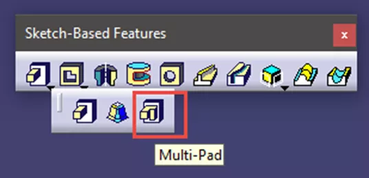
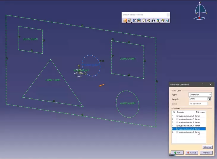
The first option is the Multi-Pad feature located in the flyout for the Pad Command within the Sketch-Based Features toolbar of the Part Design Workbench. This feature allows you to choose different pad lengths for each closed profile within the same command.
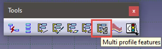
The next option is called Multi-Profile Features and it is in the Tools toolbar of the Sketcher workbench. With this command, choose which profiles you want to make independent of the rest of the sketch. Choosing this workflow will allow you to use the Pad command and select a single profile independent of the rest of the sketch.
From SOLIDWORKS Rollback to CATIA Define In Work Object
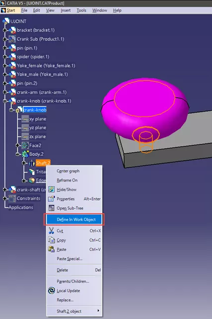
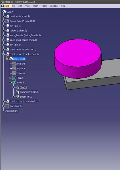
In SOLIDWORKS, the Rollback functionality allows us to temporarily suppress features and insert new features above the suppressed ones. CATIA has a similar function called Define In Work Object. To activate it, right-click on the feature you want to insert new features underneath and select Define In Work Object. Notice that the feature selected is now underlined and every subsequent feature in the Part Body is suppressed. You can now insert features just as you would with Rollback. To un-suppress the features and get back to the “current” status of the model, right-click > Define In Work Object on either the last feature of the Part Body or the Part Body itself.
Manipulating/Positioning Parts within an Assembly
When building an assembly, it is a good idea to roughly position parts before applying assembly constraints to avoid unexpected results. In SOLIDWORKS, you can drag parts parallel to your current viewing angle. In CATIA, you must define how you want to move your parts before dragging them. In the Assembly Design Workbench (Start > Mechanical Design > Assembly Design) is the Move toolbar. This toolbar provides a few options for positioning parts. In this article, we’ll focus on Manipulate and Snap.
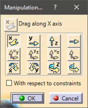
The Manipulate command allows you to translate and rotate about the base axis system of the assembly with the option to choose an axis (or edge) from your geometry. You can also pan about the assembly base planes with the option to choose a plane (or face) from your geometry. To do so, select an option from the Manipulate window (and then select the applicable geometry, if choosing the custom option) and then grab and drag the part you want to move.
![]()
The Snap command allows you to temporarily apply a Coincident constraint on a part. First, select the Snap command, select an applicable geometry on the part you want to move, and then select a relevant geometry for where you want to move it. The first geometry chosen is now coincident with the second. There is also a green arrow on the part, clicking this arrow will reverse the direction of the part. Clicking anywhere in 3D space will commit the command. The constraint is temporary, so you are free to re-snap or move the part to any new area/orientation without getting an error.
![]()
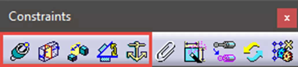
Once the parts are positioned, setting assembly constraints in CATIA is very similar to SOLIDWORKS. You can set assembly constraints using the Coincident, Contact, Offset, Angle, and Fix Constraints commands in the Constraint Toolbar.
Manipulating Assembly Mechanisms in CATIA
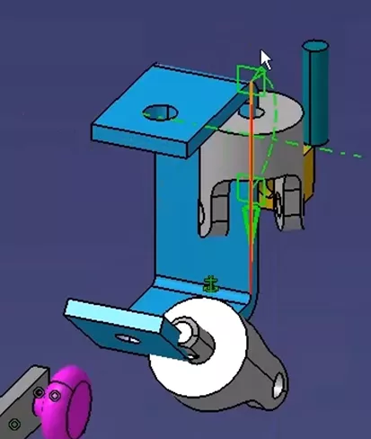
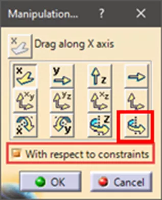
Once the parts are constrained in an assembly, you have the option to operate your mechanism based on the resulting degrees of freedom. Just like positioning parts, SOLIDWORKS lets us operate a mechanism by grabbing and dragging a part. In CATIA, you must define how you want to move the object which operates the mechanism. This can also be done within the Manipulate Command if With Respect to Constraints is activated. In the example below, to operate the mechanism one must first activate With Respect to Constraints, select the option to rotate about a custom axis, select the axis of the Pin, then grab the Knob and rotate it about the Pin’s axis. Doing so results in the U Joint assembly operating as expected.
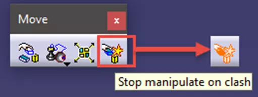
Finally, CATIA has the option to enable clash detection. Within the Move toolbar, click Stop Manipulate on Clash to activate clash detection. The orange highlight of the command notifies you that it is activated. While Stop Manipulate on Clash is active, open the Manipulate command. While making sure With Respect to Constraints is active, you can then move a part(s) until they clash with an object in the assembly. Once a clash occurs you can no longer move the part(s) in that direction and the object you are clashing with is also highlighted.
I hope you find these tips useful as you begin your SOLIDWORKS to CATIA V5 journey. If you need more assistance or prefer a structured and guided jumpstart, GoEngineer offers CATIA training, and as North America’s largest SOLIDWORKS partner, we can offer that CATIA training with SOLIDWORKS users in mind.
Related Articles
3DEXPERIENCE CATIA Tools for Assembly Design, Drawings, Sheet Metal, & More
6 Design Struggles in SOLIDWORKS that are Easier in CATIA
Composites in 3DEXPERIENCE CATIA Overview
CATIA V5 Parametric Optimization Guide
CATIA V5 vs 3DEXPERIENCE CATIA: Interface, Licensing, Installation, & Setup

About Tim Ramos
Tim Ramos is a Senior Specialist with GoEngineer based out of Denver, Colorado. He graduated from Rensselaer Polytechnic Institute in 2014 with a degree in Mechanical Engineering and Material Science. After graduation, Tim worked with Honda R&D designing the body/frame structures of their vehicles. He designed sheet metal parts using advanced surface design and plastic injection molded parts using solid part design in CATIA V5. In 2018, Tim transferred over to his CATIA Specialist career path and has been focusing on all things related to CATIA V5-6 and 3DEXPERIENCE CATIA ever since.
Get our wide array of technical resources delivered right to your inbox.
Unsubscribe at any time.