6 Reasons Designers Upgrade to CATIA
CATIA V5 (desktop-based) and 3DEXPERIENCE CATIA (platform and cloud-based), are top-of-industry CAD tools developed by Dassault Systèmes. CATIA's history with automotive and aerospace has made it especially suitable for certain design and manufacturing situations that are becoming more prevalent in other industries that may tend toward different CAD solutions. In this blog, see why many designers choose to supplement their current design solution with an upgrade to CATIA. We'll cover functionalities CATIA is known for, including the handling of large assemblies, surfacing, systems engineering, and composites, while touching on some additional capabilities.
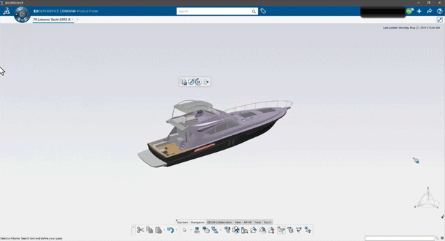
1. Large Assemblies
CATIA is well known for its ability to efficiently handle large assemblies and datasets. This is partially because CATIA loads data into the interface on an “as needed” basis. Data that is opened, initially only loads in enough definition to be visualized. From there, any other relevant data is loaded once activated or probed. As a result, the data loads faster, allowing for more fluid manipulation and quicker update processing.
For 3DEXPERIENCE specifically, the data pulls from a database upon initial opening, and a compressed copy of the data is stored locally in a cache folder. This cache is updated constantly throughout the session, up until the last save event of the data. Upon subsequent openings, the data is opened from this cache as opposed to the database, resulting in a quicker load time.
3DEXPERIENCE has an “Explore” functionality that allows users to open data in a lightweight format before opening in the “design view” or the data-heavy version. This provides the ability to visualize and sift through the relevant data to open and edit more easily.
Within the Explore app is the Volumetric Filter tool that allows users to select and open data within the proximity of a specific part or sub-assembly. This helps ease the ambiguity of opening data relevant to a specific part.
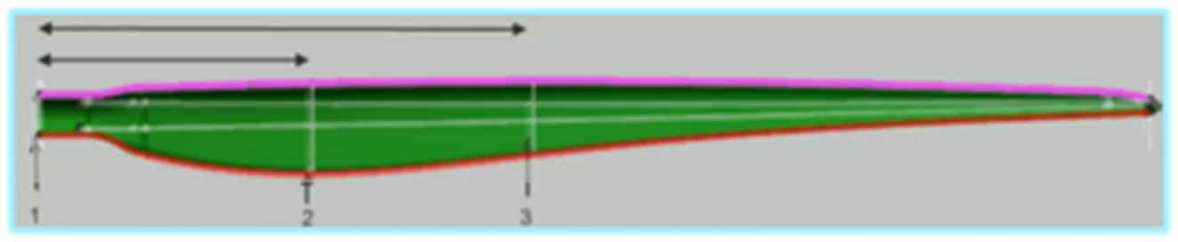
2. Surfacing
CATIA's design kernel caters to surfacing in a way that is unlike any other design tool. It’s because of this that more complicated surfacing geometry can be generated. CATIA also has more features available to the user for surfacing operations. Sweeps of a more complicated nature are simple to achieve because CATIA provides more inputs and variables to help build surface geometry. Independent surfaces can be blended with Tangent or Curvature continuity with the ability to control the surface tension at each junction. Multi-section surfaces are more easily controlled with guide curves and non-similar wireframe geometries can be more easily blended.
3. Systems Engineering
Within the CATIA portfolio is the ability to perform Model-Based Systems Engineering (MBSE). MBSE is a design strategy that captures the deliverables from all stakeholders, models the internal and external behavior of the system, and includes the physical 3D of the assembly representing the system.
Systems Engineering, in its early stages, focuses on requirements for a project’s success from various viewpoints. These are defined early in the design process and addressed throughout development. Designing in this way ensures validation of the system based on deliverables from all stakeholders by considering operations, performance, testing, manufacturing, cost and schedule, training and support, and disposal.
Within a model developed in CATIA are four different types of data, represented each by their own node in the design tree, that are used to consider all these elements. These factors are referred to as RFLP for Requirements, Functional, Logical, and Physical. Each factor has its own specific data that is captured within each factor’s node of the design tree.
(R) Requirements: This node of the tree allows users to list, track, and validate the conditions that must be met for the product to be successful and meet all stakeholder’s needs. Stakeholders can be users, customers, shareholders, and certification agencies, to name a few.
(F) Functional: Data Flow Block Diagrams are used to describe the output of the system based on the given inputs. Each function is described and decomposed. With access to the Dymola Behavior Modeling App, the behavior can also be simulated.
(L) Logical : The components of the system and their interfaces are described here. The Logical node of the design tree enables users to associate a 3D model to each component and use those models to allocate space and system layout activities. The behavior of each component is specified using the Dymola Behavior Modeling Language.
(P) Physical: The Physical node of the design tree will house the 3D CAD data for the system.
The CATIA brand now also includes No Magic MBSE solutions such as Cameo Systems Modeler and MagicGrid, which are also making their way into new industries. You can learn more about that from our CATIA Magic product page.
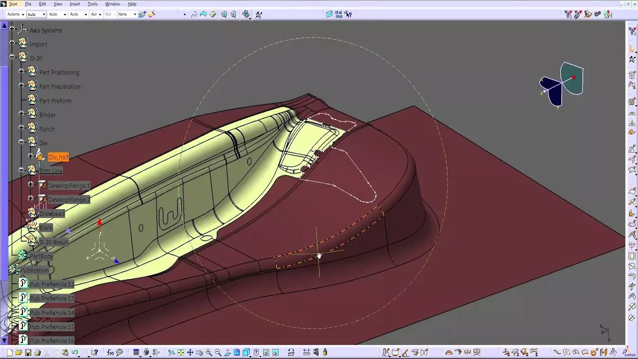
4. Composites
CATIA provides a range of composite design capabilities to develop composite parts that are unavailable in many other CAD packages, such as:
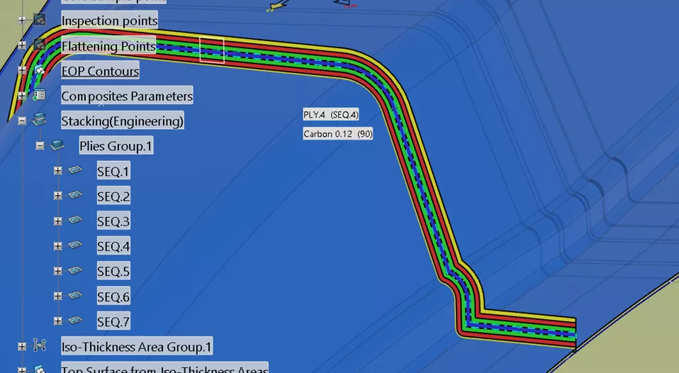
Creating the Composite Definition – Define Ply contour, material, fiber direction, stackup order, interactions between stackups, drop-off patterns, manufacturing and engineering edge of part, solid and top surface, etc.
Probing the Design – Record or gather on-the-fly information for composite or physical properties (area, mass, volume, center of gravity). Also provided is the ability to create scaled section cuts or exploded views of the Plies.
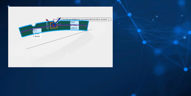
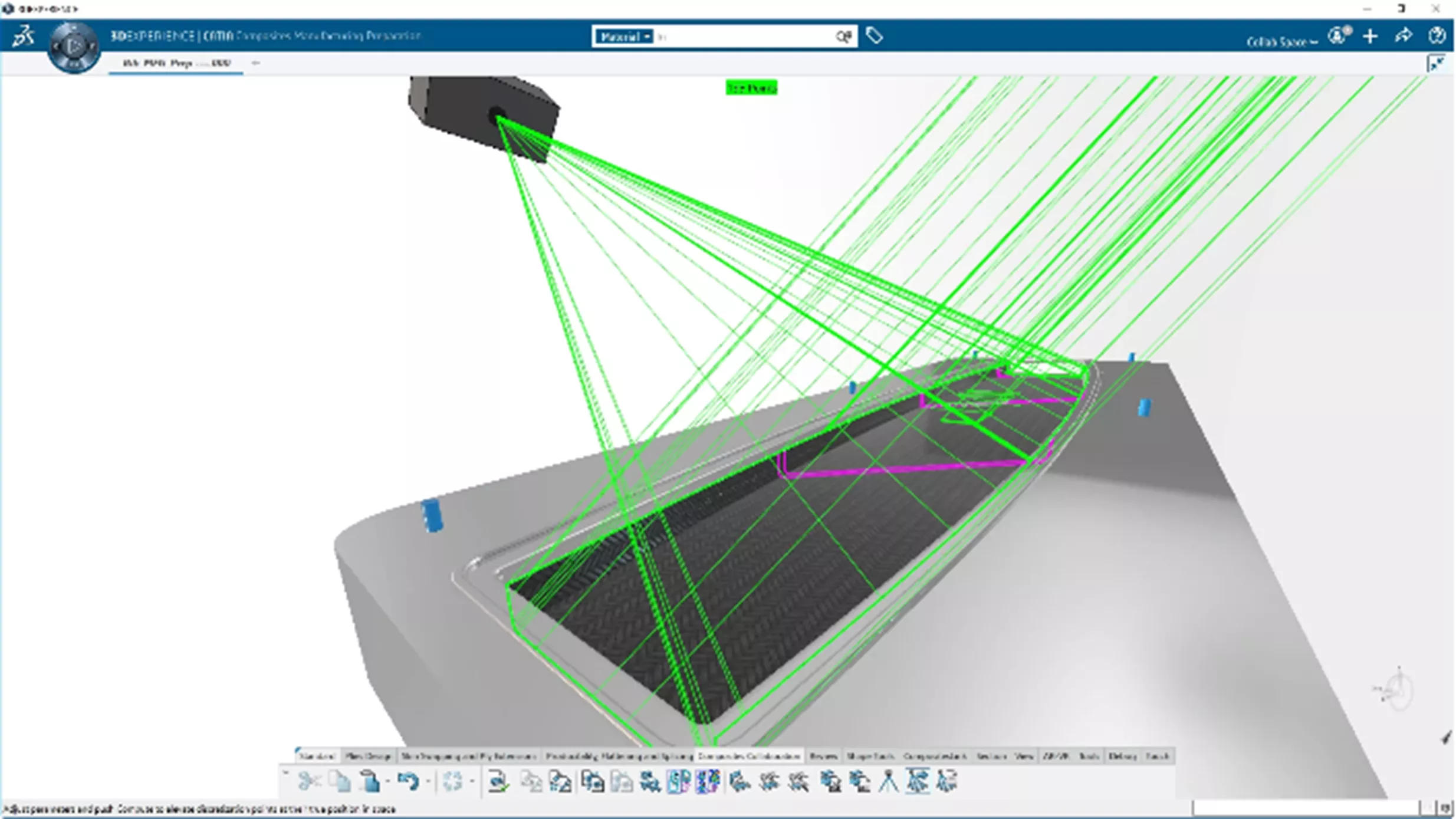
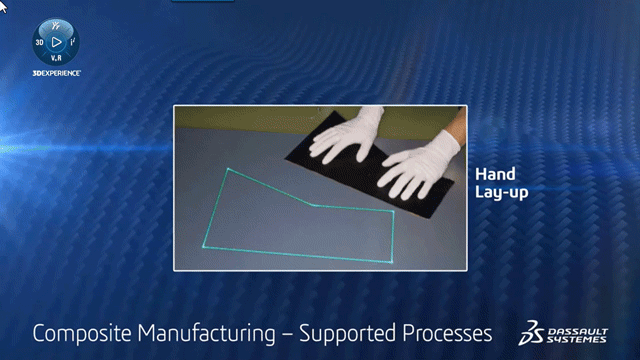
Checking the Manufacturability – The Producibility for Hand Layup tool provides the ability to simulate the hand layup process and check for fiber deformation as well as sufficient roll width to accommodate the flat pattern. Issues that arise from excessive deformation or insufficient roll width can be mitigated by generating darts and implementing cut-pieces/splices, respectively.
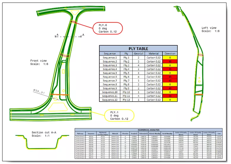
Creating Engineering and Manufacturing Documentation – CATIA provides the ability to create a Composite Drawing (engineering drawing) that shows the part in its final state with all composite Plies. Additionally, users can create a Ply Book (manufacturing drawing), which separates the definition across multiple drawing sheets to better facilitate manufacturing instructions and standard operating procedures.
Exporting Composite Definition for Reuse – CATIA facilitates the reuse of composite definitions by providing the ability to export to a table. This table can then be imported and configured against the new part to emulate the legacy data. Furthermore, composite parts created in CATIA V5-6 can be imported into 3DEXPERIENCE CATIA with full design history.

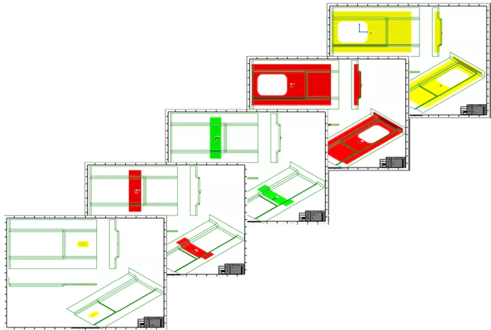
Flat Pattern Export for Laser Projection – CATIA can export the flat pattern of your Plies to .cal or .ply format compatible with VIRTEK Laser Projection Systems. These systems project accurate outlines of each Ply onto the tooling surface to facilitate the hand layup process.
5. Importing Points/Splines/Lofts (Additional Capabilities)
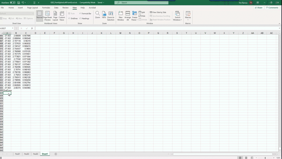
CATIA provides the ability to import points into the CAD model. However, also within CATIA is the option to expand on this capability. Out-of-the-box, CATIA provides an Excel table embedded with macros that allow users to input point coordinates and simultaneously create splines from those points. Users can also generate lofts from those splines.
6. Lattice Structure for Lightweighting (Additional Capabilities)
3DEXPERIENCE CATIA Lattice Designer provides the ability to generate a lattice structure for the purpose of “lightweighting” parts intended for 3D printing. These parts can be seamlessly integrated with structural validation tools within 3DEXPERIENCE and can be readily exported to a 3D printer-ready format such as STL, RMF, or 3MF.
If you would like to know more about functionalities within 3DEXPERIENCE CATIA and CATIA V5, as well as our range of offerings at GoEngineer, our 3DEXPERIENCE CATIA product page and our CATIA Buying Guide are great places to start.
Editor's Note: This article was originally published in July 2023 and has been updated for accuracy and comprehensiveness.
Discover Advanced Design with CATIA & More.
Learn how to raise the bar and stay competitive with generative design, design optimization, totally new CAD modelers, and additional CATIA capabilities here.
3DEXPERIENCE CATIA WHITEPAPER
10 Reasons 3DEXPERIENCE CATIA Gives Mechanical Engineers An Advantage
Having the right tools for the right job can massively increase engineers' productivity, and there's no time to lose in today's competitive environment.
3DEXPERIENCE CATIA companies can experience:
- A 20% to 50% gain in productivity thanks to superior modeling and assembly management capabilities
- Seamless workflows and faster processing with cloud-based data management and high-performance cloud computing
- Up to a further 30% improvement in productivity thanks to a unified modeling and simulation environment and design for manufacturability
Download this whitepaper for a closer look at what makes CATIA the ultimate mechanical design tool.


About Tim Ramos
Tim Ramos is a Senior Specialist with GoEngineer based out of Denver, Colorado. He graduated from Rensselaer Polytechnic Institute in 2014 with a degree in Mechanical Engineering and Material Science. After graduation, Tim worked with Honda R&D designing the body/frame structures of their vehicles. He designed sheet metal parts using advanced surface design and plastic injection molded parts using solid part design in CATIA V5. In 2018, Tim transferred over to his CATIA Specialist career path and has been focusing on all things related to CATIA V5-6 and 3DEXPERIENCE CATIA ever since.
Get our wide array of technical resources delivered right to your inbox.
Unsubscribe at any time.