Abaqus - Modeling Arbitrary Shaped Beam Cross Sections
When modeling and working with a slender structure, there are three options available, each more computationally efficient than the next:
- Model the structure using continuum solid elements (the simpler approach).
- Utilize shell elements, whenever feasible, particularly for hollow beam structures that can be mid-surfaced.
- Model the beam structures as lines, utilizing beam elements that incorporate the beam's cross-sectional properties into the formulation.
If you opt for the third alternative, your analysis will be significantly more efficient since beam elements possess far fewer degrees of freedom compared to continuum solid elements.
Therefore, the cross-section properties must be provided in order to define these elements. This enables Abaqus to calculate the stiffness and inertial properties of the beam. However, using the pre-defined cross-sections in Abaqus is not an option when working with beams having arbitrary cross-sectional shapes.
Meshed Beam Cross-Sections steps in to rescue in this situation. In this article, we go through the steps needed to model arbitrary shaped cross-sections and verify the results.
Model
The model below consists of four vertical beams bounded by two plates, with a cut plate at the center shaped around the beams. Adjacent to the model is its mesh, which, despite the relatively simple geometry, is quite fine. A total of 219,837 elements were needed to have three elements in the through-thickness of the plates and the vertical beams. It becomes evident why working with solid elements is not the best approach. The figure below shows the geometry of the model, with the vertical beams and shelves meshed with solid continuum elements.
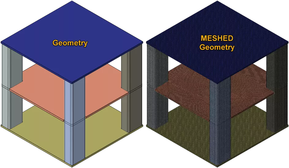
To assess the accuracy of beam elements, three models will be run. In each model, the vertical beams will be simulated using solid continuum elements, shell elements, and beam elements. On the other hand, the three shelves, which consist of two plates and a middle cut plate, will be modeled as shell elements for all three models.
The cross-section for the beam, shown below, is simple but is not part of Abaqus' pre-defined cross-sectional shapes. The Box cross-section from the pre-defined options could be used to estimate this shape, but the rounded corners would not be taken into account since it is a rectangular shape with sharp 90-degree angles.
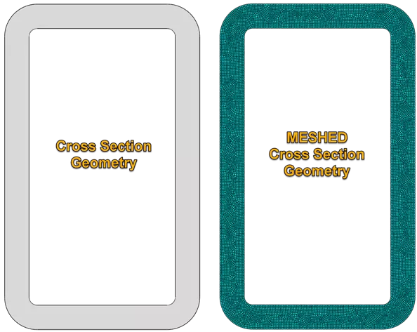
To use this cross-section shape, the beam cross-section should be meshed with two-dimensional warping elements. From this mesh, Abaqus calculates the beam cross-section properties which include axial, bending, torsional, and transverse shear stiffness, as well as mass, rotary inertia, and damping properties, and the location of the centroid and shear center. These cross-sectional properties will then be written to a text file called jobname.bsp.
Procedure
To get the cross-sectional properties and have it written to a jobname.bsp file, follow the instructions below:
- Mesh the cross-section with two-dimensional warping elements.
- Assign a simple elastic material.
- Instance the part and write the input file.
You do not need to add any loading or boundary conditions since the procedure used here will be added manually in the input file. - Add the following step to the input file:
*Step, perturbation
*Beam Section Generate
*End Step
Running this will generate the jobname.bsp file, which you can then include in the analysis as a section property for beam elements. And so, in the input file, you would add:
*Beam General Section, elset=SetName, section=MESHED
*Include, input=jobname.bsp
Results
A uniform pressure of 10 MPa is applied to the middle cut plate, with the bottom plate fixed. The point at which the beams meet the cut plate is kinematically coupled with the cutout of the plate. The top and bottom ends of the beams are also coupled with the top and bottom plate, respectively.
The animation below illustrates the presence of solid, shell, and beam elements from left to right, respectively. All three types of runs are presented for verification purposes. The solid model (on the left) remains unchanged, while the shell model (in the middle) has both beams and plates midsurfaced. The beam model (on the right) has midsurfaced plates and beam elements used to model it.
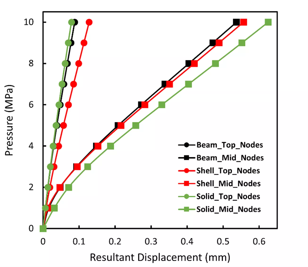
The four couplings where the beams meet the cut plate are used to calculate the average displacement. The same process is carried out for the four couplings located at the top plate. The 10MPa pressure that is incrementally applied is plotted against the averaged displacement. By examining the plot below, it can be seen that all three models show good agreement for the pressure vs displacement profile.
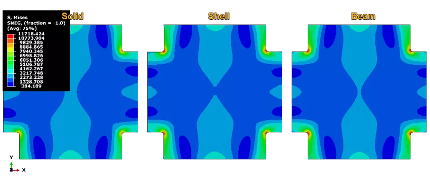
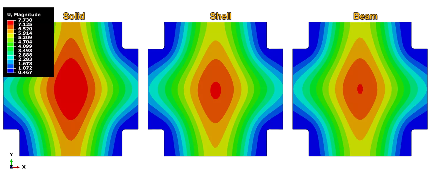
In addition to the plot above, the von Mises stress profile, along with the resultant displacement profiles, are plotted for all three models. Again, all these contours show great agreement.
To highlight just how efficient beam elements are, it is worth noting the different sizes for these models, as well as the time it took to run the analysis. (Shown in the table below)
| Solid | Shell | Beam | |
| Number of Elements | 92,058 | 15,157 | 9,142 |
| Time (s) | 319 | 75 | 71 |
The total time between the shell and beam model might not seem too significant, but that is only because the geometry is fairly simple, and the model is small. With bigger and more complicated models, the difference between the two will become significant. From this table, it can be seen that it only took 10% of the number of elements from the solid model to get accurate results with the beam model.
Note:
- To calculate the total simulation time (WALLCLOCK TIME) for each model, the initial time increment was set to 1 and the incrementation criterion was set to automatic. However, to obtain the incremental step time pressure shown in the plot above, the incrementation was fixed at 0.1.
- The number of elements in the table above under Solid corresponds to the number of elements for the vertical beam models considered solid continuum while the shelves as shell elements. This number is different than the number mentioned at the beginning of this article (219,837) which corresponds to the entire model as solid continuum elements (including the shelves).
Conclusion
In this article, we have highlighted the importance of Meshed Beam Cross-Sections as a powerful tool for modeling arbitrary shaped cross-sections in Abaqus. By following the procedure outlined, we were able to accurately model the cross-sectional properties of a beam with a non-predefined shape, which allowed for efficient analysis while maintaining accuracy. The results of our analysis were verified by comparing them with those of solid and shell elements, and we found a high level of agreement between all three models in terms of deformation and stress contour plots. Thus, it is evident that Meshed Beam Cross-Sections is a crucial technique that enables engineers to achieve accurate results of complex structures with arbitrary cross-sectional shapes.
Ready to get started with Abaqus? Read our Abaqus buying guide or reach out to one of our GoEngineer simulation experts to find the right tool for you! If you’re not ready to use Abaqus yourself, you can still take full advantage of its benefits through FEA consulting from GoEngineer.
Related Articles
Understanding Abaqus Material Behavior
FEA and CFD Analysis Software: What to Know Before You Buy
FEA Critical Speed Analysis & Rotor Dynamics
Abaqus FEA: Powerful Finite Element Modeling

About Bilal Abdul Halim
Bilal Abdul Halim is an Application Engineer at GoEngineer specializing in Abaqus. Bilal holds a Bachelor’s degree in Mechanical Engineering and a Master's degree in Experimental Fluid Mechanics where he studied the effects of corona discharge on viscous oil using particle image velocimetry. When not at work, Bilal is usually playing ping pong or trying different restaurants.
Get our wide array of technical resources delivered right to your inbox.
Unsubscribe at any time.