FEA Critical Speed Analysis & Rotor Dynamics
Designing rotating machinery requires a thorough analysis of potential vibrational feedback that could occur in the system during operation. If proper precautions are not taken, excessive vibrational excitations in rotating systems can create catastrophic failures. In this article, see how we used 3DEXPERIENCE STRUCTURAL roles and Abaqus FEA software to perform an analysis workflow focusing on the identification of critical speeds where large vibrational excitations are most likely to occur.
Vibration In Rotating Systems
When it comes to rotating machinery, the mitigation of vibration is critical to the structural soundness of the device and the safety of those in the vicinity. A primary concern of engineers who design rotating machinery is the vibration due to unbalance within the system.
The most tangible example of this sort of unbalance can be seen (and heard) when a rotating top-loaded washing machine is unevenly loaded. Think of the loud and rhythmic “Chunk-Chunk-Chunk” that comes about when washing a load of towels that weren't adequately distributed around the rotating axis of the washer.
That rhythmic sound is likely the spinning washer operating at a critical speed. At this critical speed, the drum will exhibit a type of periodic displacement from the spin axis known as a whirling mode. If that displacement is large enough, it can lead to an unpleasant and repeated sound of the tub bouncing off the housing for the washer.
The impact forces generated by the rotor-housing interaction can lead to many undesirable effects, such as damage to the housing, abrasion of any surface treatment for the rotor or housing, and even a decrease in the fatigue life for the bearings due to the induced reaction forces. In short, that rotor-housing interaction is not only obnoxious but it can also become quite troublesome for rotating system designers themselves.
To demonstrate the considerations that rotating system designers must be aware of, we’ve included results from an example workflow for a critical speed analysis of an unloaded simplified washing machine.
Rotor Dynamics Whirl Mode Shapes
Figure 1 demonstrates one of the whirling modes of vibration that exists in a very simplified washing machine model.
Figure 1: Harmonic Animation of a whirling mode shape. In this analysis, the outer-housing functions as a display body and does not influence the response of the rotating tub & shaft
For simplicity’s sake in developing the whirling mode shape animation, the tub was run in an empty configuration without water. In reality, the true response of the system would largely be influenced by the amount of water and clothing material placed in the system. With this in mind, we can nonetheless visualize the manner in which the center of mass for the tub orbits around the ideal axis of rotation. The shape of vibration is sometimes referred to as the mode shape or whirling mode shape in the case of rotor dynamics.
Every whirling mode shape has a corresponding whirling frequency. Put simply, if the operating speed of the rotating machine is roughly equal to this whirling frequency, the system will experience large vibrational displacements and whirl in the same manner as the whirl mode shape.
Campbell Diagrams & How to Determine Critical Speeds
Whirling frequencies and whirl mode shapes are determined by extracting the complex natural frequencies of the system. Typically, analysts will define the operating range for the rotating system and extract the complex natural frequencies at multiple speeds in order to understand how these values change as the stress state evolves. The most common tool that depicts the change in natural frequency values due to centrifugal stress is a Campbell diagram.
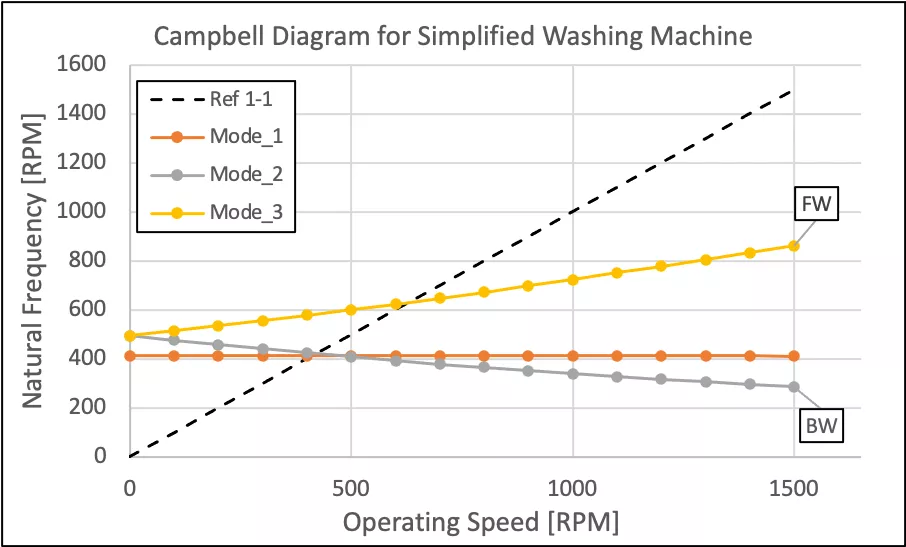
Figure 2: Campbell Diagram for Simplified Washing Machine. See next figure for depiction of whirling mode shapes
Figure 3: Depiction of first three mode shapes. Mode_1 exhibits torsional vibration. Mode_2 and Mode_3 exhibit Lateral Vibration
Figure 2 depicts a Campbell diagram as generated for the simplified washing machine model. Figure 3 depicts the mode shapes as plotted in the Campbell diagram. Three important details can be drawn from the Campbell diagram:
- The torsional vibrational mode (Mode_1) is insensitive to changes in the stress state due to centrifugal loading. Additionally, this type of vibrational response is not usually excited by unbalance within the system, as is the case in lateral vibration modes (Mode_2 and Mode_3).
- The lateral vibration modes split as the stress state of the rotating system increases. Mode_2 is classified as a backward mode, where the center of gravity for the system orbits in a path opposed to the spin direction about the ideal spin axis. Mode_3 is classified as a forward mode where the center of gravity orbits in a path in line with the spin direction for the system. Figure 4, shown below, visualizes the directional classification of a forward or backward whirling mode.
- The intersection of the “Ref 1-1” operating line with either of the lateral vibration modes is referred to as a critical speed. These are the operating speeds at which one would expect large vibrational displacements for the system and higher synchronous vibrational forces passed into the bearings due to unbalance in the rotor.
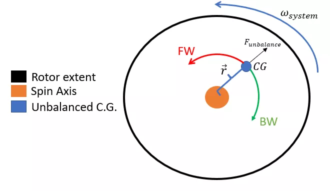
Figure 4: Depiction of whirling direction (top view)
How to Deal with Critical Speeds
The heart of a critical speed analysis centers around the development of the Campbell diagram (shown in Figure 2). In the case of our simplified washing machine, we’ve identified critical speeds around 425 RPM and 625 RPM for the backward and forward modes, respectively. With this information, designers of rotating machinery can then take multiple approaches to mitigating the synchronous vibrational response due to unbalance at these speeds. These strategies include, but are not limited to:
- Increasing the stiffness of the bearings to push the critical speeds to a higher value outside of the operating range.
- Investigating damping properties for the bearings to mitigate the amount of vibrational force passed into the static structure through the bearings.
- Varying the stiffness and mass of the structure in order to modify the base value for the natural frequencies (thicker shaft, lighter weight drum material, etc.)
- Reduce the mass unbalance in the system such that the forces and displacements generated at the critical speed are reduced.
Critical speeds are fundamental to the operation of a rotating machine. If proper considerations are given, designers may be able to avoid the unfortunate scenario of having a critical speed within their operational range. However, in certain scenarios, designers may not know ahead of time exactly how mass is distributed about their system.
This is the case in the washing machine example. In the development of the washing machine design, a maximum unbalance was likely assumed for normal operating conditions. When the “Chunk-Chunk-Chunk” noise comes about, it indicates the end user likely did not meet the required balancing tolerance.
In other words, the amount of vibrational displacement is directly correlated with the amount of unbalance in the system. Thus, when you redistribute the towels evenly, the amplitude of vibrational displacement decreases, that loud “Chunk-Chunk-Chunk” noise disappears, and the problem is solved.
Value Added to Client
In this article, we’ve presented a simplified example of the outputs generated for clients seeking a critical speed analysis of rotating machinery. Generally, these projects are iterative in nature, where we develop a baseline model to determine the critical speeds their design exhibits within their operating range.
From there, additional iterations and perturbations to the model are performed in a controlled manner in order to determine the influence of each variable on the value of critical speeds. These potential design changes in simulation allow for the investigation of the design space in a more cost-effective and timely manner compared with physical prototyping alone.
Additionally, the critical speed analysis technique requires the pre-stressing of the system between natural frequency extraction steps. Because of this, we can provide an approximation to the steady-state stress conditions for the system at speeds across the profile. This has led to the identification of potential design issues for our clients prior to the fabrication of design prototypes.
Conclusion
Rotor dynamics is a complex subject with multiple branches of analysis. This article has focused on one workflow for the identification of undamped critical speeds where the system is most likely to exhibit large synchronous forced vibrations due to unbalance within the system. Additional analyses within the realm of rotor dynamics include but are not limited to:
- Forced response analysis, which is the steady-state characterization of system stress due to synchronous forced vibration.
- Critical speed mapping, where the stiffness of the bearings becomes a chosen parameter and multiple critical speed analyses are performed.
- Transient analysis of the rotating system during a startup or shutdown procedure.
- Transient analysis of the rotating system as it accelerates through a critical speed.
With all this to consider, leveraging the expertise of a trusted consulting service can be critical for leveraging the most capable and efficient tools for the job and maintaining a timely development schedule. GoEngineer has a proven history of providing actionable feedback to rotating system designers aiding in their engineering design process.
For additional reading concerning the development of a rotor dynamics model using the Abaqus/Standard solver:
- How to create rotor dynamic models in Abaqus/Standard
- Abaqus Technology Brief: Rotordynamics analysis using Abaqus/Standard
- Abaqus/CAE plug-in for plotting Campbell Diagrams

The Virtues of Virtual Prototyping
Download the report to see how top manufacturers leverage virtual prototyping tools to decrease costs and shorten product development cycles.
Related Articles
Abaqus FEA: Powerful Finite Element Modeling
Abaqus Solvers: Empowering Engineers in Every FEA Scenario
FEA and CFD Analysis Software: What to Know Before You Buy
SOLIDWORKS Simulation vs Abaqus: When Should You Upgrade?

About Thomas Schlitt
Thomas Schlitt is a Simulation Specialist at GoEngineer and has a passion for understanding the governing physics behind systems in our world. He primarily leverages the advanced simulation tools within the 3DEXPERIENCE Platform for his simulation consulting opportunities. Prior to adopting the 3DEXPERIENCE Platform, he brought with him approximately 5 years of Abaqus and finite element analysis experience.
Get our wide array of technical resources delivered right to your inbox.
Unsubscribe at any time.