Add Detail to 3D Prints with SOLIDWORKS Offset Surface and Thicken
When using a single-extrusion 3D printer, it can be helpful to better define edges for post-print painting. Before I 3D print a CAD model, I look for dividing edges or boundaries for painting different colored surfaces.
In SOLIDWORKS, Offset Surface can quickly be used with the Thicken command to raise a surface. You do not have to be a Surfacing expert to use this technique. Unlike extruding a boss that has a flat face, this method can raise a wavy or organic surface. It can be used for raising text to show initials, a part number, or any other kind of labeling. It can be used to help make small details easier to paint.
To create an offset surface in SOLIDWORKS:
- Click Offset Surface from Surfaces Toolbar or select Insert, Surface > Offset Surface
- In the PropertyManager, select surfaces or faces in the graphics area to offset
- Set a Value for Offset Distance and click OK.
Note: You can copy a surface with an offset value of zero.
This classic model, created by Mike J. Wilson, shows the geometry and the dialog box.
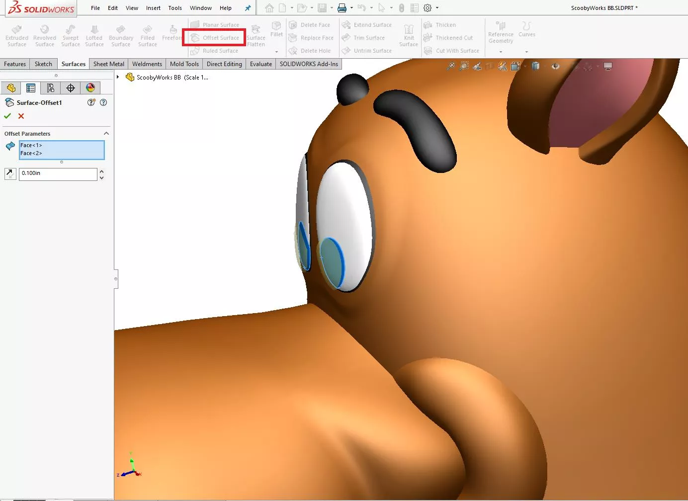
The direction of the offset can be flipped by switching the arrow just like an extruded boss or cut. Pay attention to the offset value, which will be used again for the next step.
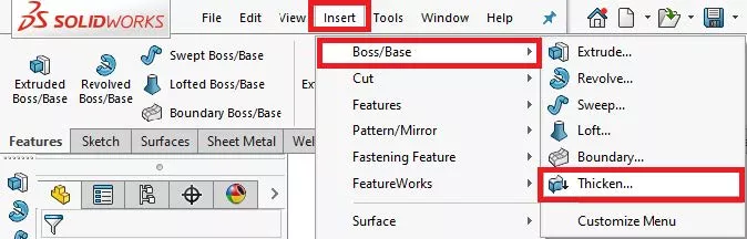
To thicken the newly created offset surface:
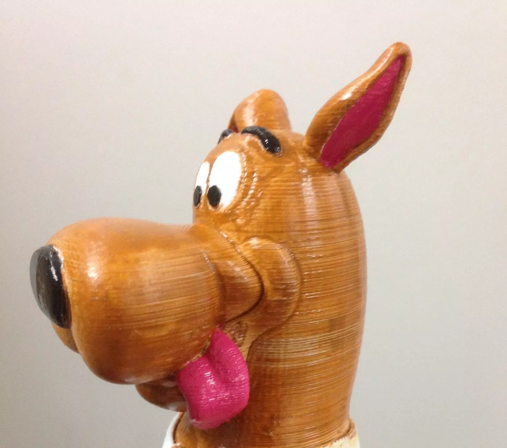
- Click Insert, Boss/Base, Thicken… (shown below)
- In the PropertyManager, select the surface or face in the graphics area to thicken (only one surface per Thicken feature)
- Review preview display, select which side of the surface to thicken Set a Value for the thickness, match the offset surface value, and click OK.
Merge results will keep the Solid Body count the same number as it was before. For Merge results to work correctly, make sure to geometry does intersect with the main body.
This image shows the preview of thicken direction.
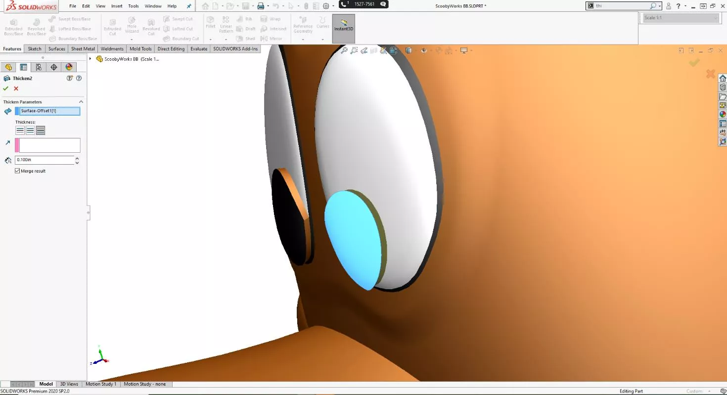
This next picture shows the actual 3D printed model painted with the raised surfaces around the face. The pupils were slightly raised, using the steps above, to give some depth but also to help make painting easier. This modeling technique is efficient and easy to use. You do not have to trim, extend, or knit surfaces to get it to work correctly.
The thickness value can be small to add a subtle effect like here or a larger thickness depending on how much depth you want to add. After creating the raised surface(s) always check your work in your 3D slicer software to make sure it is raised enough for the desired effect. When it comes to painting, steady hands and patience are key. For small detail, a magnifying lamp and micro brushes really make a difference.
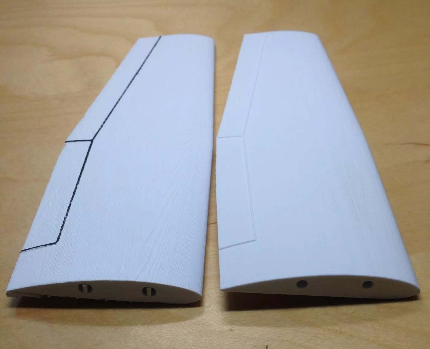
This second example shows the edges of a wing’s control surfaces raised up. Even without painting, it already helps highlight the edges. Trying to paint these edges without them being raised up could be a slow, painful process, trying to keep the lines straight.
What if there are not any defining surface edges to select?
The Split Line Curve (Insert > Curve > Split Line Curve) feature can be used to “cosmetically” cut or scribe surfaces to make individual faces that can be raised or lowered. Without going into detail here on the Split Line Curve feature, creating a 2D sketch and using the Projection option is usually the fastest way to get split faces. The last thing to show is how to lower a surface or remove material. A surface can be copied and then use Thickened Cut to remove material. Copy the surfaces using the Offset Surface (Offset Surface with zero offset value) as shown below:
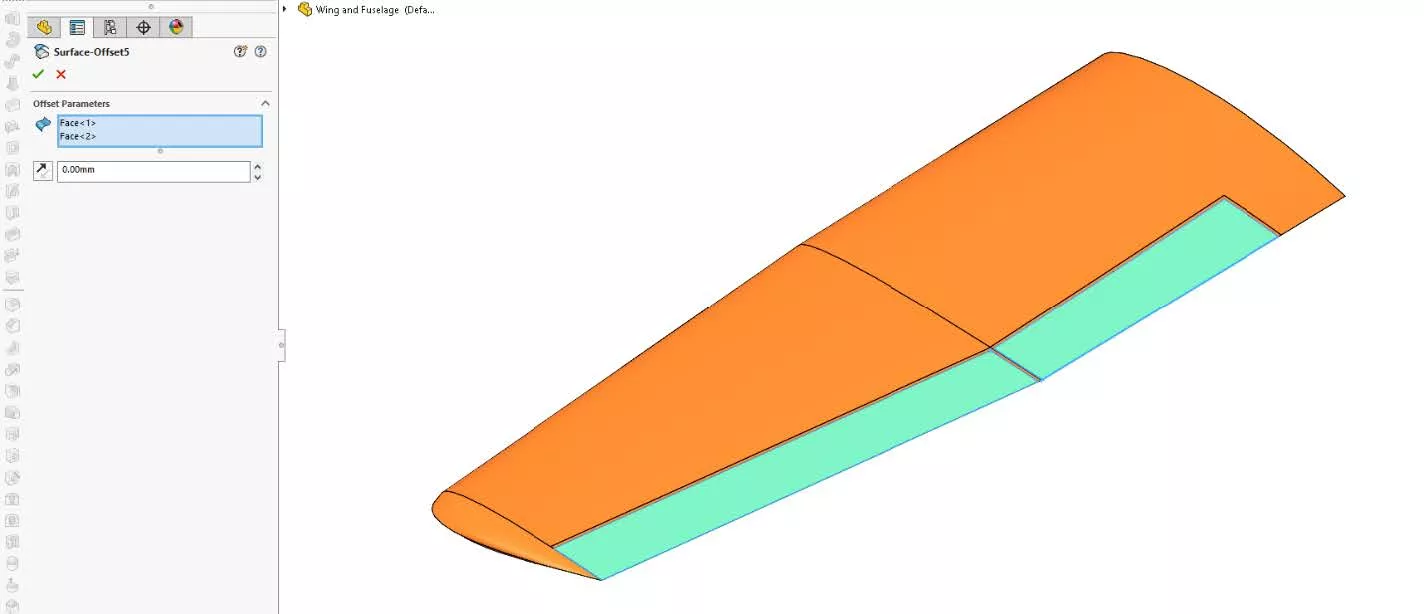
Notice how you can select multiple faces for this step. The next step is to use Thickened Cut. The removal of material must be done one face at a time.
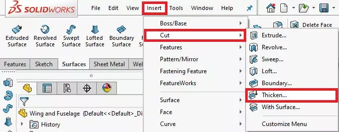
To thicken cut with the newly created copied surface:
- Click Thickened Cut from Surfaces Toolbar or Click Insert > Cut > Thicken… (shown below)
- In the PropertyManager, select the surface or face in the graphics area to cut (only one per Thicken Cut feature)
- Review preview display, select which side of the surface to thicken cut Set a Value for the thickness to get the desired height
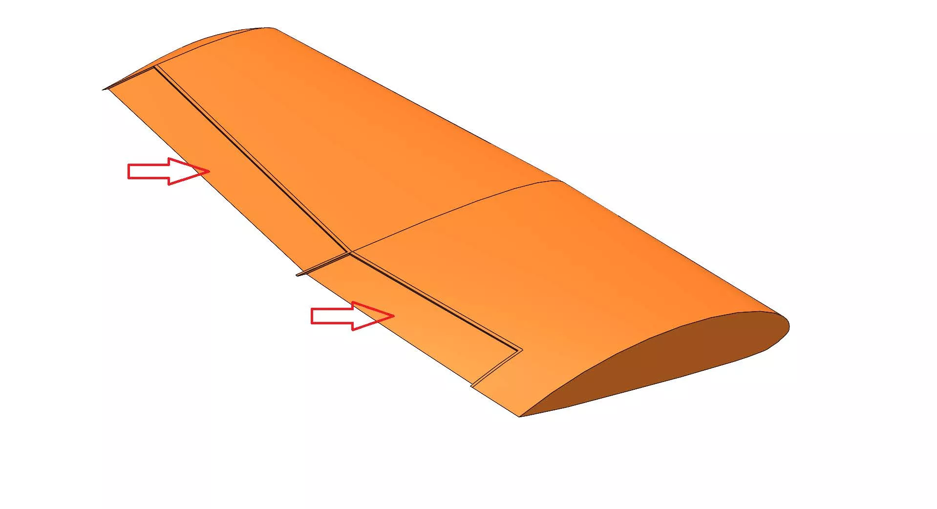
Here is the wing example after using the Thickened Cut feature twice to lower the two control surfaces highlighted below.
Try these techniques above to get better results showing detail in your models and to have an easier time painting your 3D prints for fun or for work.
More 3D Printing and SOLIDWORKS Tutorials
SOLIDWORKS at Home: DIY CAD Projects
Artichoke Lamp Shade Modification: Design Hacks
Creating a 3D Printed Race Medallion Hanger Using SOLIDWORKS

About Maurice Cherian
Maurice Cherian is Technical Support Engineer at GoEngineer. He was introduced to CAD while working for the Navy. Maurice has over seventeen years of Software Training and overall CAD experience. He has been using SOLIDWORKS since 2008 and is a certified expert and instructor. He provides SOLIDWORKS training and Tech Support. Maurice is active in the SOLIDWORKS User Group Community in San Diego, presenting and hosting multiple times over the last eleven years.
Get our wide array of technical resources delivered right to your inbox.
Unsubscribe at any time.