Calculating the Center of Pressure in SOLIDWORKS Flow Simulation
When calculating torque or center of pressure in two dimensions, forces are typically aligned cleanly with the X-Y coordinate plane. However, in more complex 3D cases, those forces are rarely aligned evenly and come in at angles.
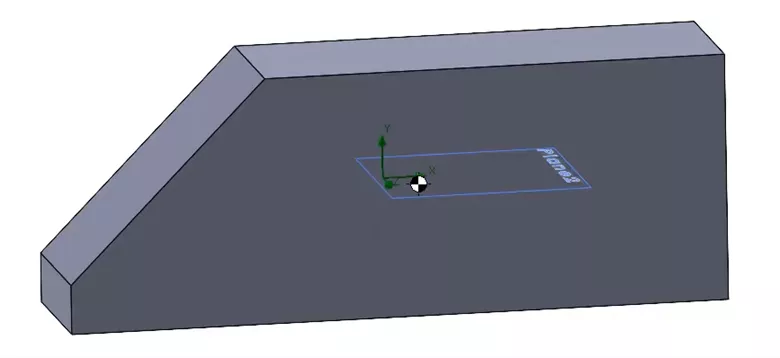
You can watch more about calculating torque in two and three dimensions on our YouTube channel but what if we want to tackle this problem in SOLIDWORKS Flow Simulation? Let’s set up a study in Flow Simulation to find the center of pressure. For the setup, we’ll choose to have the velocity flow in the X direction and create goals to monitor the forces acting in X, Y, and Z, as well as torques acting around the green coordinate system in the model, shown below.
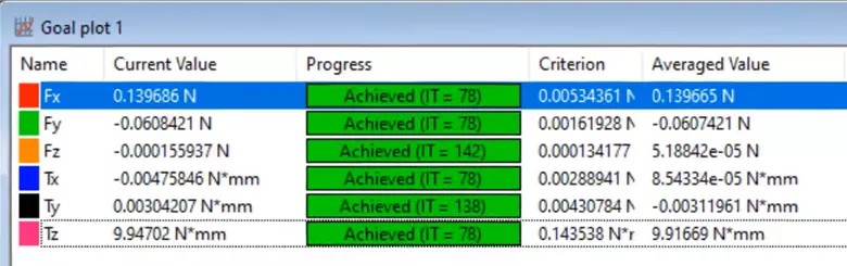
When we run the study, we can see that the force acts mostly in the X direction, with a little bit in the negative Y direction, and most of the torque is happening around the Z axis.
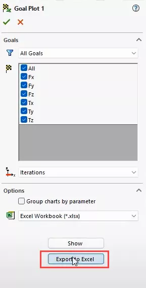
Once that is done, we can create a Goal Plot and export the values to Excel.
From there, we will copy and paste the values into the spreadsheet we created, and decide on a chord plane vector in the Y direction.
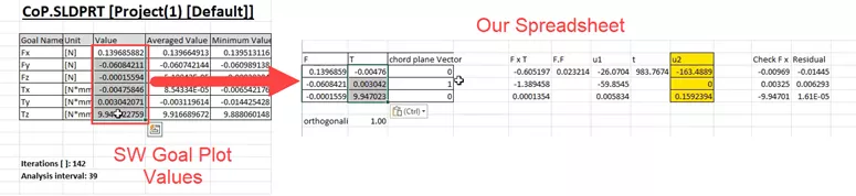
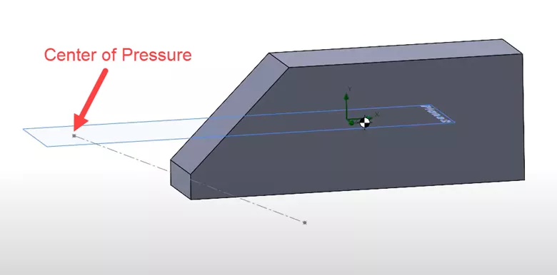
The values in u2 are the location of our center of pressure. If we want to see the line of action, we can plot the two points in SOLIDWORKS and see what it will look like. To do this, create a 3D sketch, add two points, and set their coordinates. From there, connect those points using a construction line and see the line of action for the force. The point that lies on the chord plane is the center of pressure.
We can check this by placing a coordinate system at each of the points, as well as another off in space. Then, we can calculate what the moments around each point sums to in those locations.
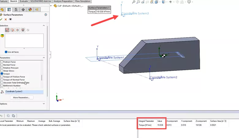
To do this, create a Surface Parameter, choose ‘Torque’, and select each of the coordinate systems to see what values they give.
CoordinateSystem3 is the one that is off in space and gives a torque value of 19.536 N^mm.
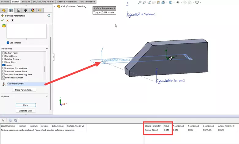
CoordinateSystem1 and CoordinateSystem2 are the two points on the line of action and both give a value close to 0 of 0.016 N^mm.
Keep in mind:
- If your goal is to determine how stable your model is, finding the center of pressure may not be necessary. Instead, locate the origin about the center of mass and look at the moments around that location. We can see which way the body will rotate.
- If your model is 2D or contains a lot of symmetry, simpler hand calculations can be used instead of those in the spreadsheet we used.
Expand Your SOLIDWORKS Flow Simulation Skillset
5 Steps to Take Before Every SOLIDWORKS Flow Simulation Analysis
Different Pressures in SOLIDWORKS Flow Simulation
SOLIDWORKS Flow Simulation Templates
SOLIDWORKS Flow Simulation Fluid Mixing Tutorial

About Tashayla Openshaw
Tashayla Openshaw is a SOLIDWORKS Technical Support Engineer based out of our Headquarters in Salt Lake City, Utah. She earned her Bachelor’s degree in Mechanical Engineering from the University of Utah in 2018 and has been part of the GoEngineer family since February 2019.
Get our wide array of technical resources delivered right to your inbox.
Unsubscribe at any time.