Introduction to SOLIDWORKS Mates: Standard, Advanced, & Mechanical
Mates are constraints that hold components together in SOLIDWORKS assemblies. Like relations in sketches, they are geometric conditions relating one entity to another. Each Mate requires you to select two (or more) faces, edges, or vertices on separate parts to build a constraint holding those parts together.
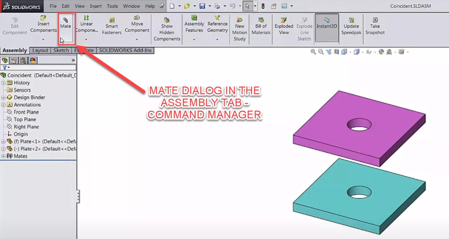
Access the Mate dialog by clicking the Mate button in the assembly tab of the CommandManager. The paper clip (shown below) is the standard SOLIDWORKS symbol for mates; any time you see it, you're dealing with mates.
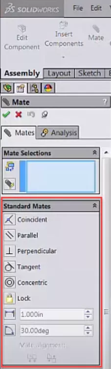
List of Standard Mates in SOLIDWORKS
There are several different types of Standard Mates in SOLIDWORKS:
- Coincident
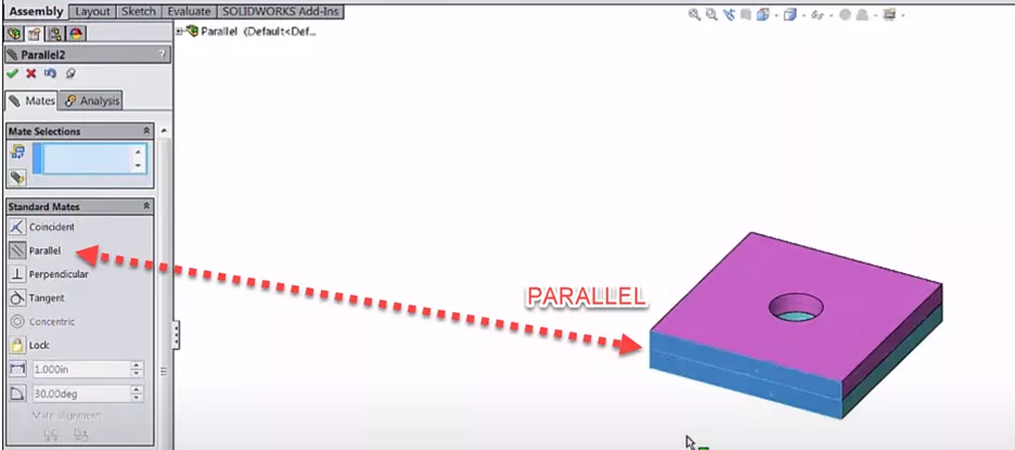
- Parallel
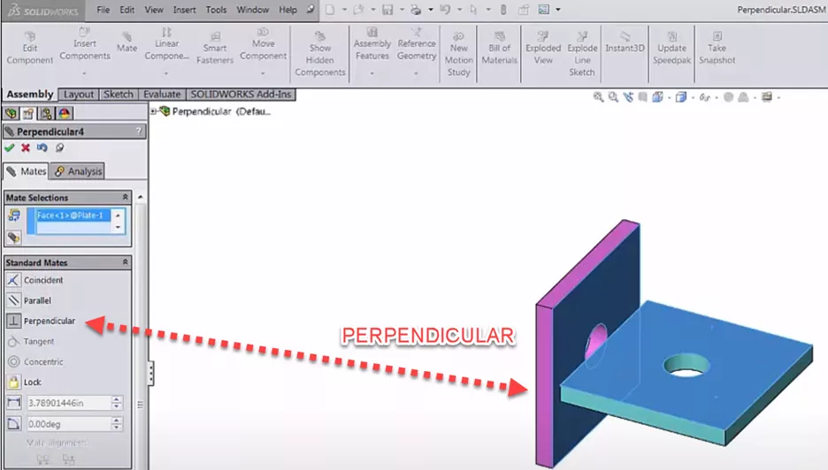
- Perpendicular
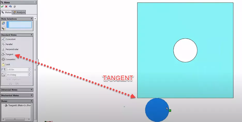
- Tangent
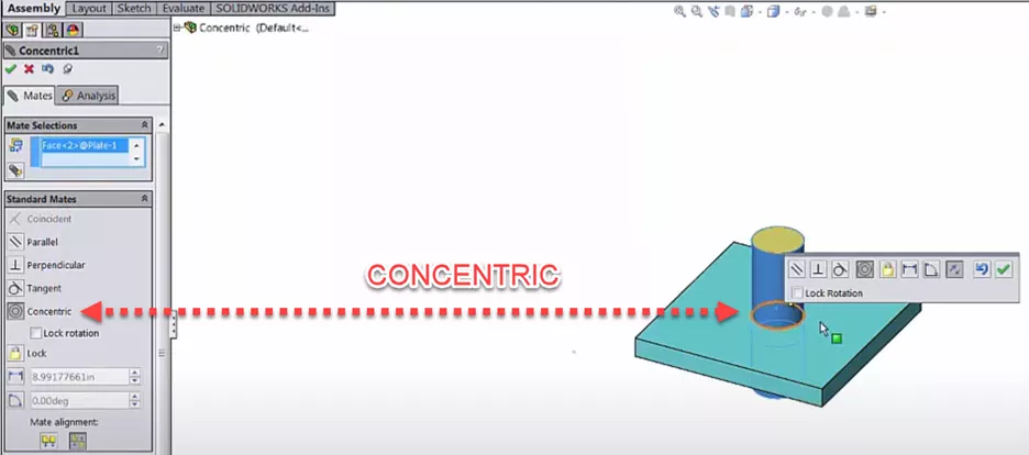
- Concentric
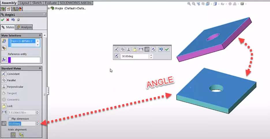
- Angle
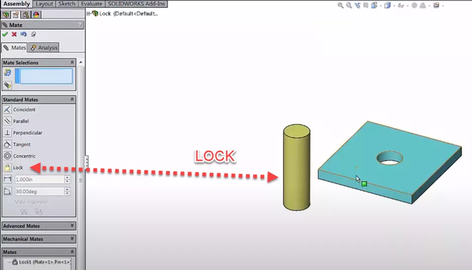
- Lock
Almost all of these are 3D versions of the same geometric constraints used in sketch relations.
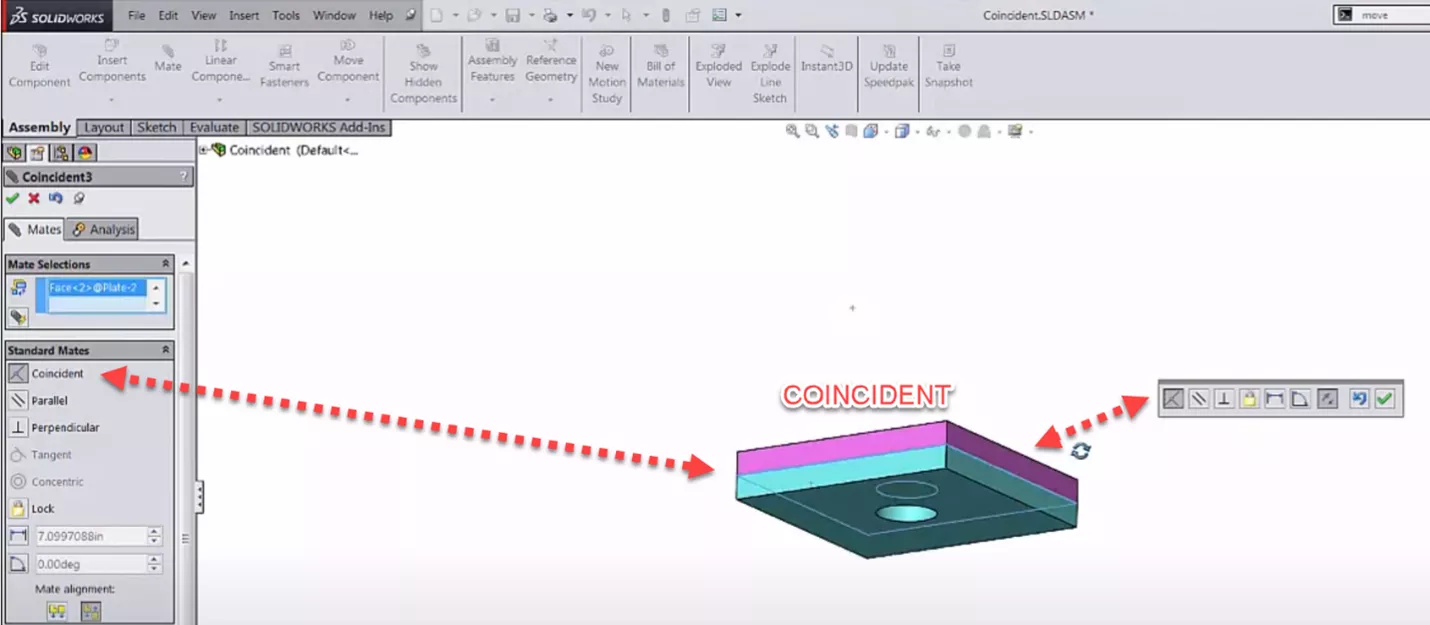
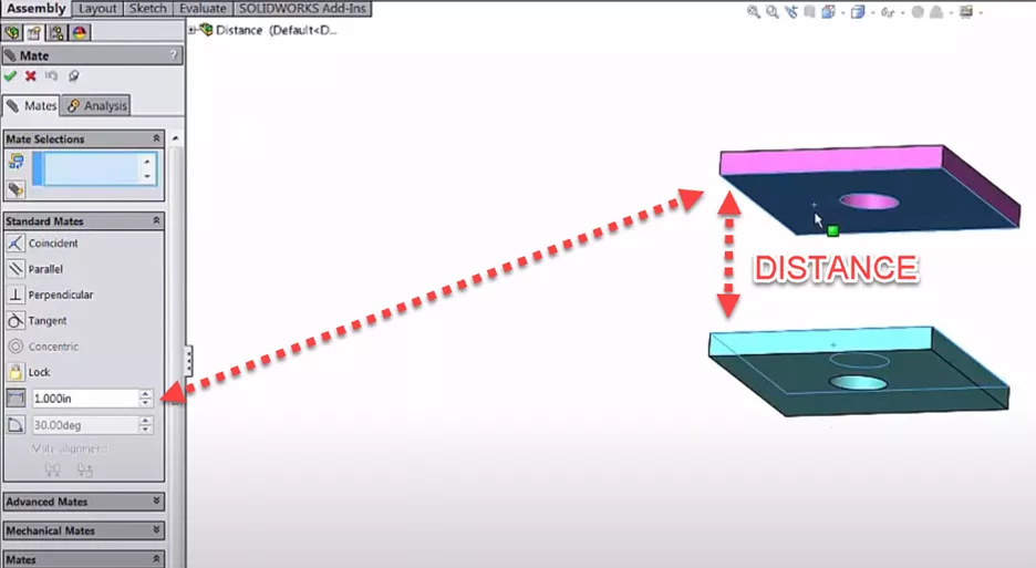
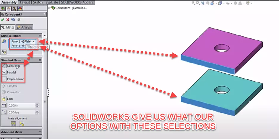
When a Mate is formed, a dialog pops up near the cursor providing several options. Depending on what was selected, the popup allows you to change the Mate type, enter a distance or angle, flip the Mate alignment, undo, or finish the Mate.
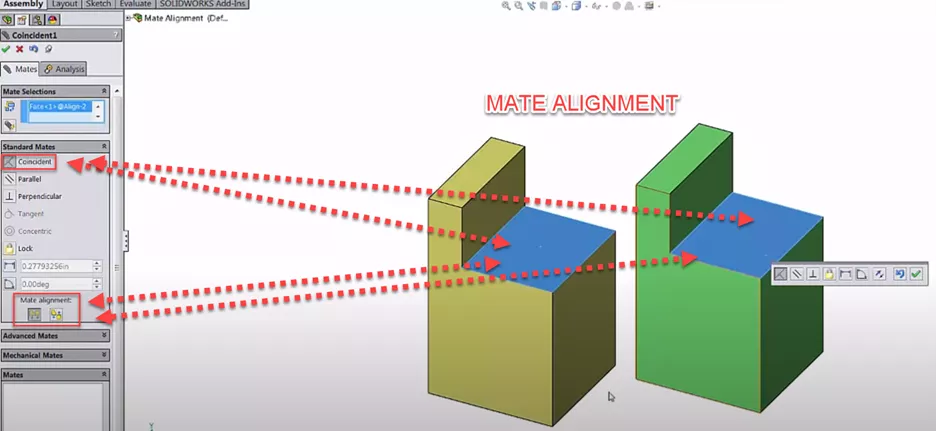
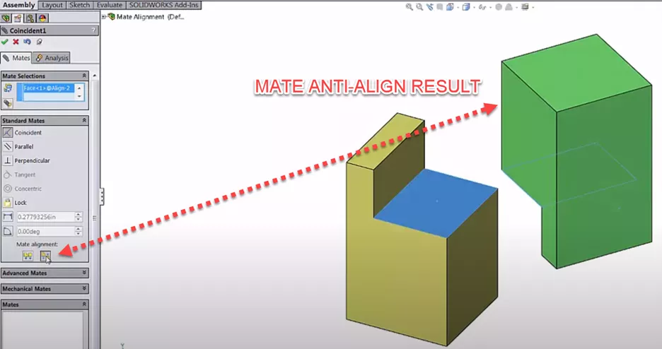
Pay close attention to Mate alignment. Most Mate conditions (e.g., Coincident) result in two possible part orientations: Aligned or Anti-aligned. The orientation closest to the current Part placement will be chosen by default. However, you can flip the Mate alignment by toggling the Align and Anti-Align buttons.
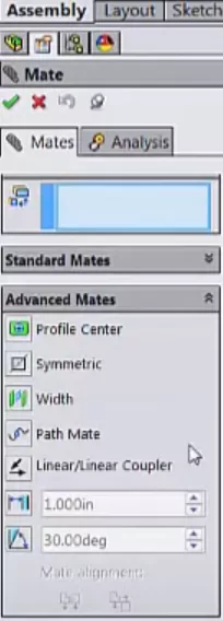
List of Advanced Mates in SOLIDWORKS
Listed below these Standard Mates are Advanced Mates. These often do the job of multiple basic mates but have more complicated effects.
- Profile Center
- Symmetric
- Width
- Path Mate
- Linear/Linear Coupler
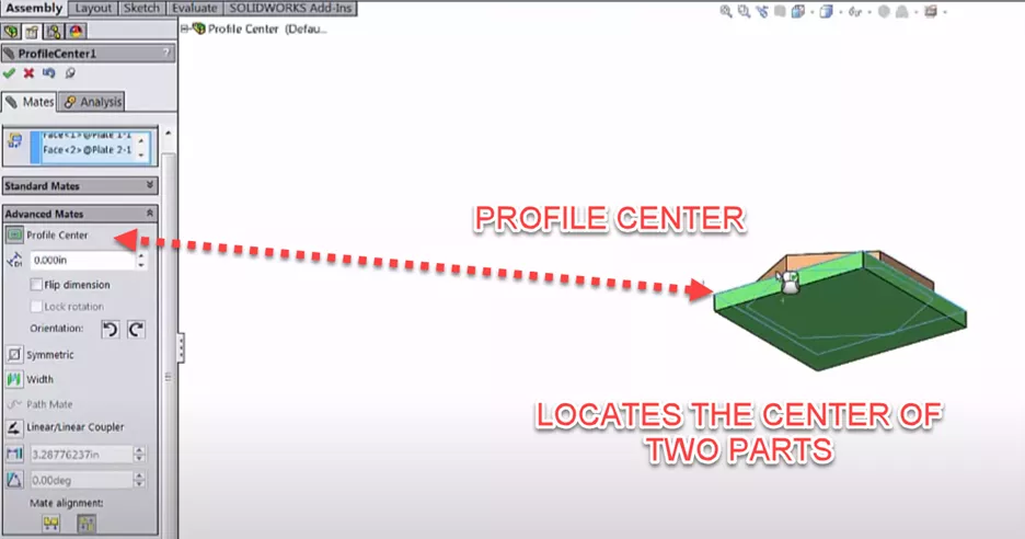
The Profile Center Mate aligns two parts based on their geometric centers but is limited to parts with simple planar shapes.
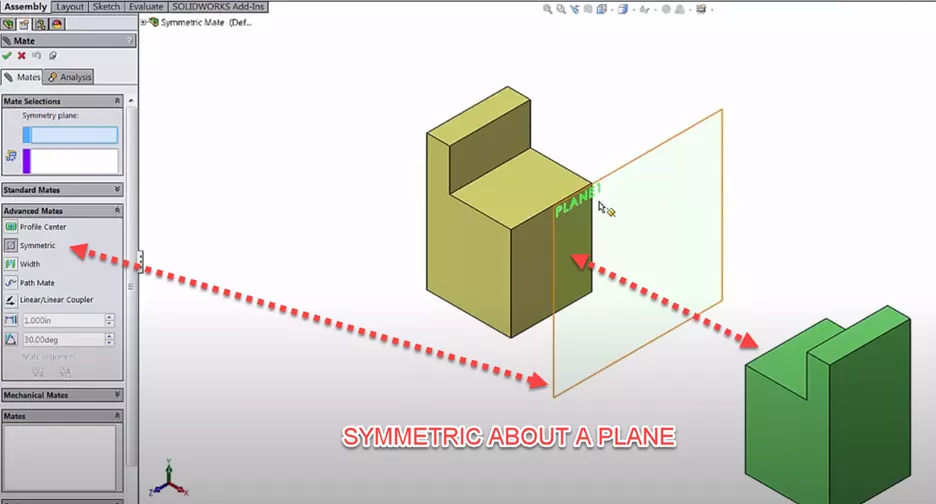
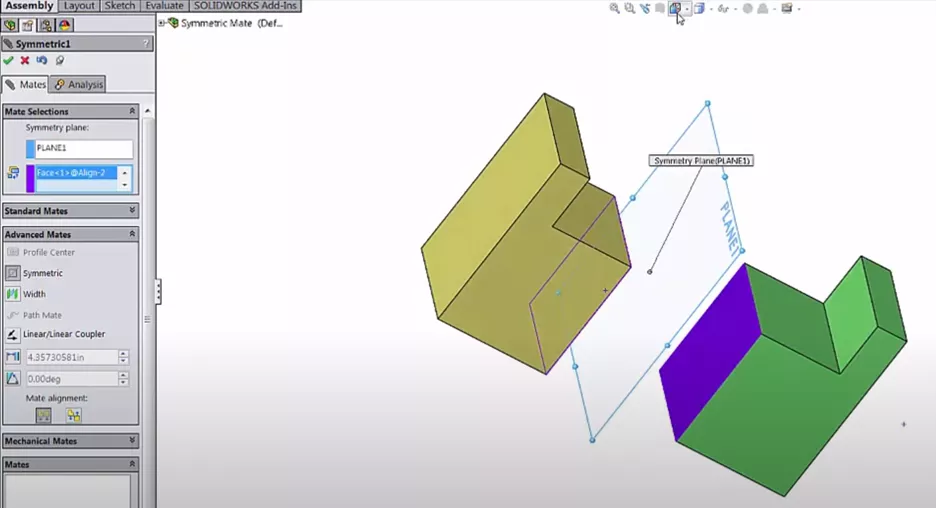
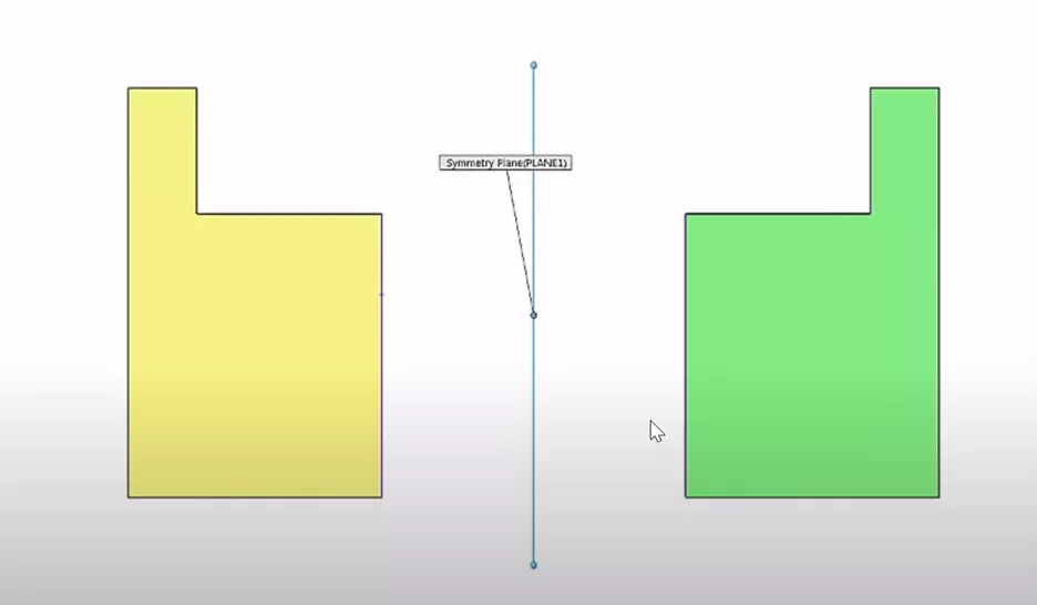
The Symmetric Mate makes two entities symmetric across a plane or face (like a 3D version of the Sketch Relation).
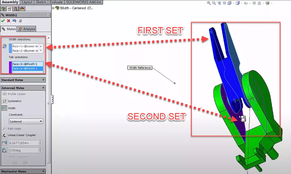
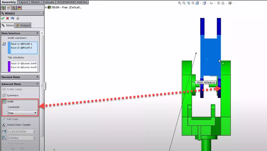
The Width Mate is extremely useful. It requires you to select two faces on each of two separate parts, and centers the two faces of one part midway between the two faces of the other.
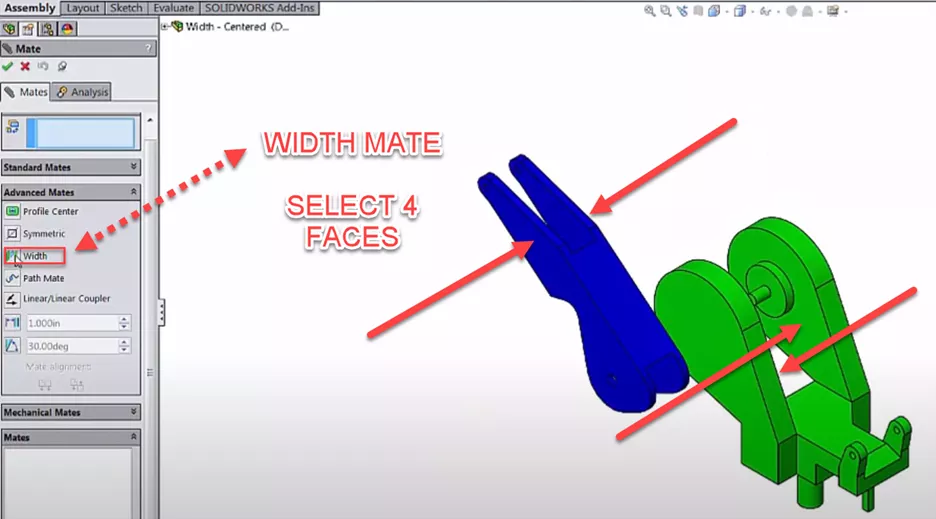
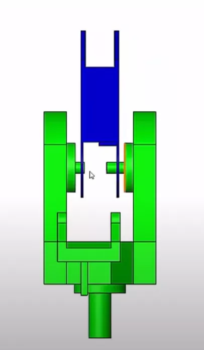
Building this intelligence into that condition allows the parts to stay centered in the assembly, even when the dimensions of parts change.
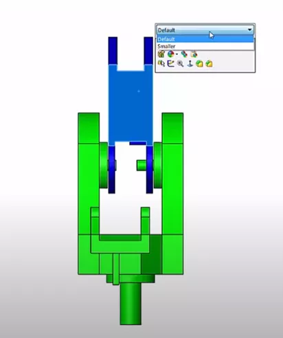
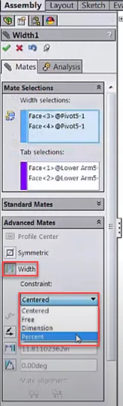
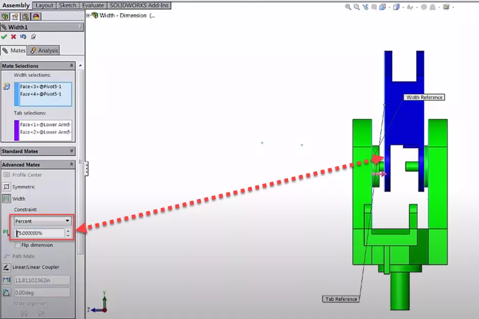
The Width Mate dropdown contains additional options (Centered, Free, Dimension, and Percent).
Dimension and Percent are useful when you want the intelligence of a Width Mate even when parts to be slightly off-center.
Free allows us to move between the two surfaces.
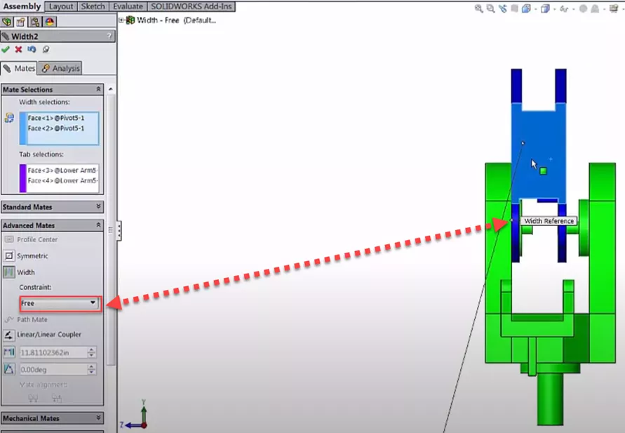
Free treats the outermost faces as boundaries for the innermost faces or vice versa, allowing us to have real-world limits to our assembly's motion.
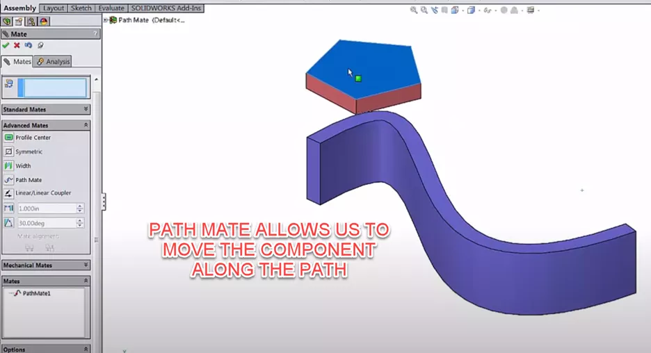
The Path Mate constraints a vertex of one part to the edge of another. It is another way to show motion and limits in an assembly.
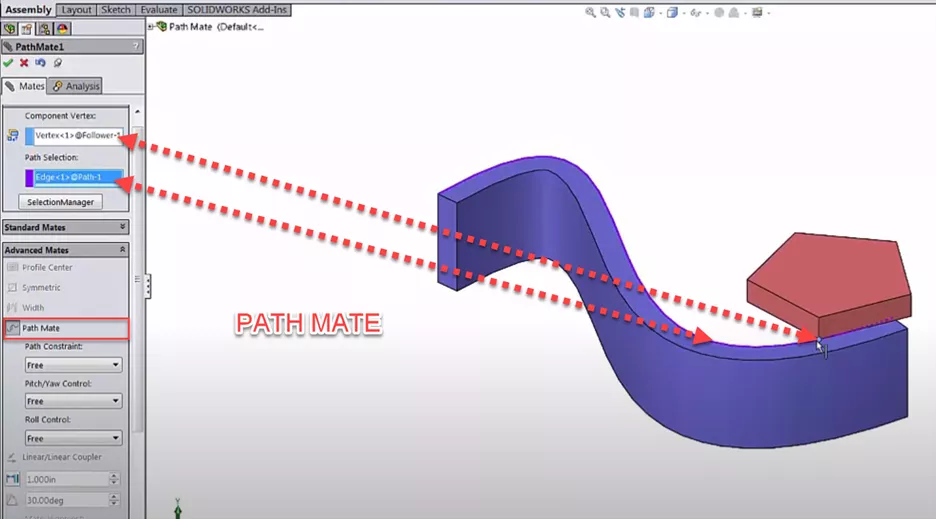
Suggested Article >> SOLIDWORKS Path Mate Explained
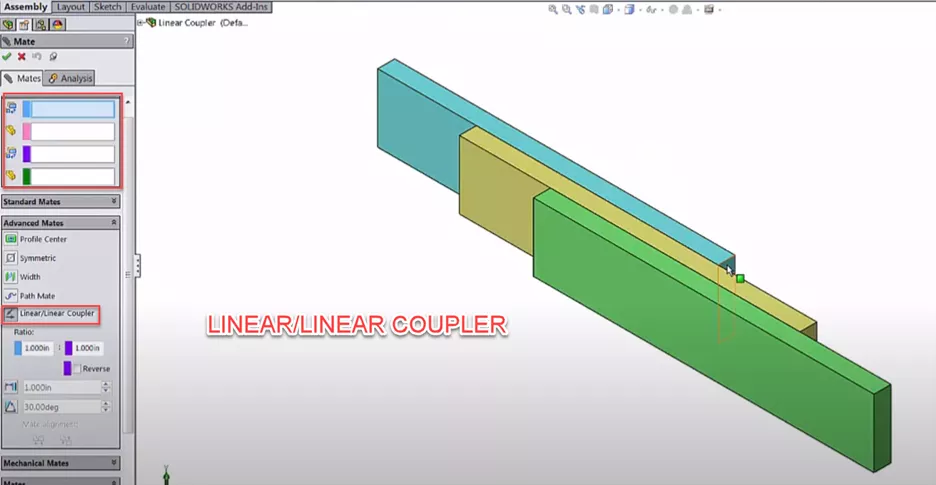
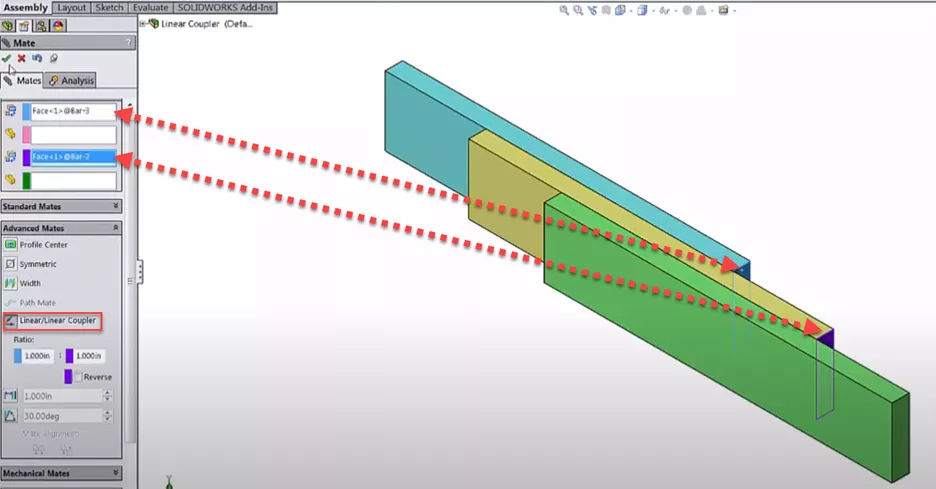
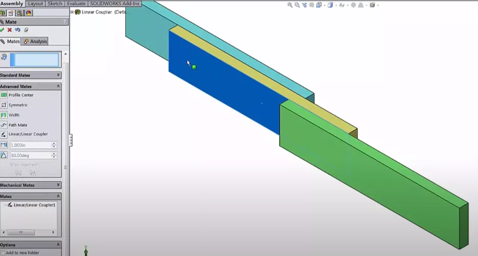
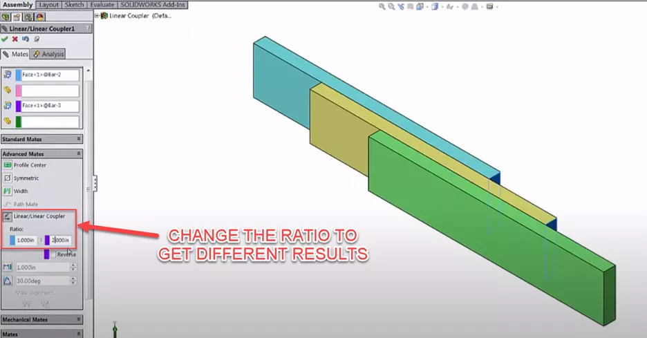
The Linear/Linear Coupler Mate couples the linear motion for two components. We could make the parts move together in a linear direction or at a ratio.
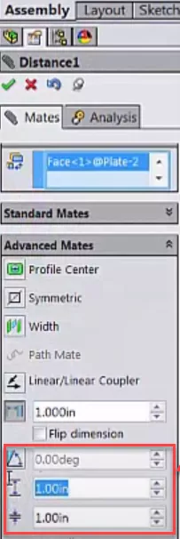
Limit Mates allow you to set minimum and maximum distances or angles that two faces can have from each other. This is a great tool for representing real-world motion limits in a SOLIDWORKS assembly.
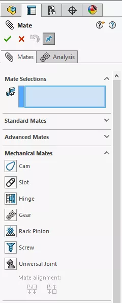
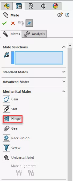
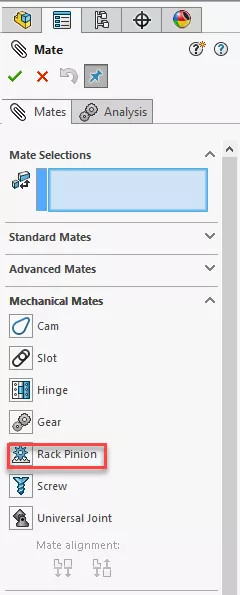
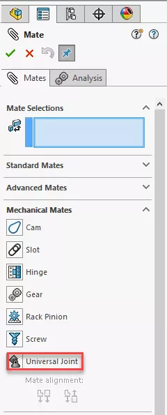
List of Mechanical Mates in SOLIDWORKS
Mechanical Mates allow us to make mechanical relations that go beyond simple geometric conditions. Mates listed under the Mechanical Mates dropdown include:
- Cam
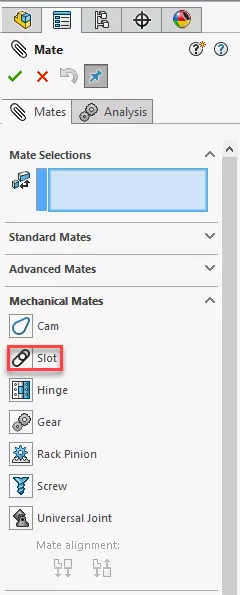
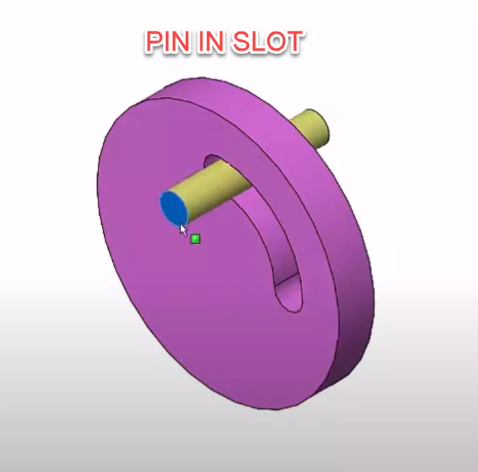
- Slot
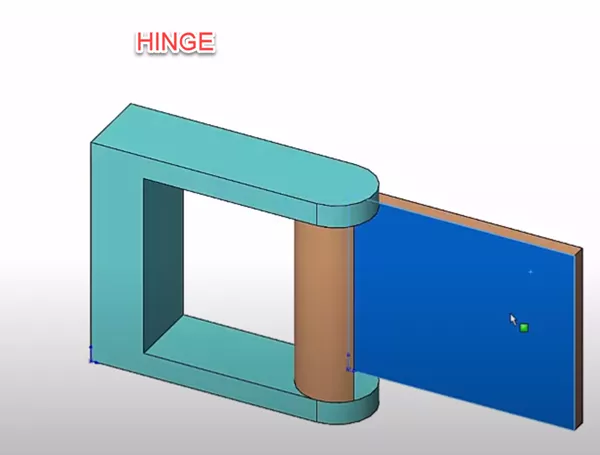
- Hinge
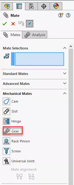
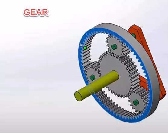
- Gear
- Rack Pinion
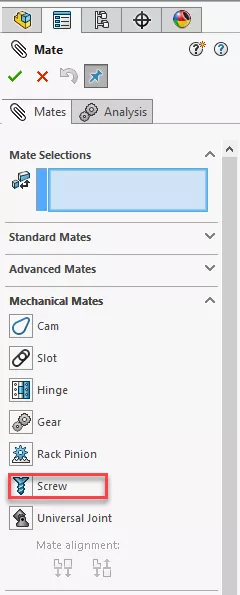
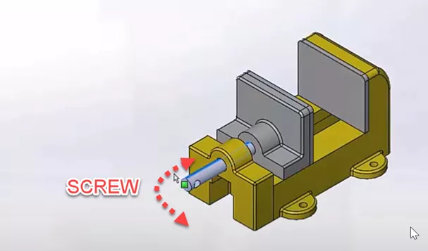
- Screw
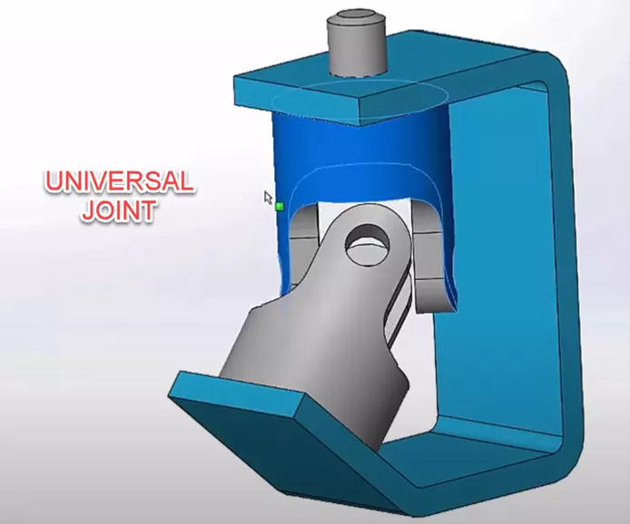
- Universal Joint
The Cam Mate allows us to create a relation between a cam and follower to simulate real mechanical systems, not just motion based on ratios.
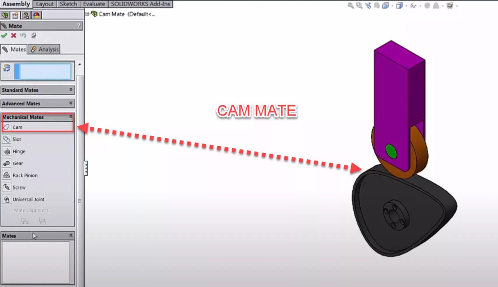
Additional Mates under the Mechanical Mate dropdown include Hinge, Gear, Rack Pinion, Screw, Slot, and Universal Joint.
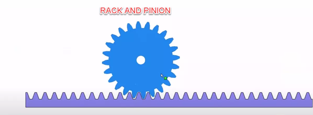
Suggested Article >> SOLIDWORKS Rack and Pinion Mate Tutorial
All assembly mates are stored in the Mates folder in the FeatureManager Design Tree. Here we can delete, suppress, or edit them just like Features in the part. This is useful if you find out after the fact that you have made the alignment wrong or used a Coincident Mate when it should have been parallel.
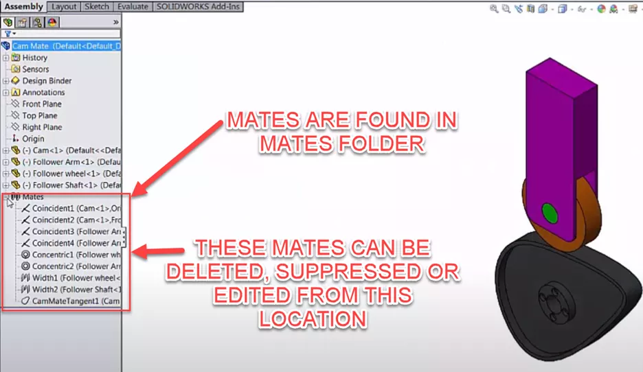
Additionally, the mate information is duplicated for any specific component and can be found in a folder at the part level in the FeatureManager Design Tree.
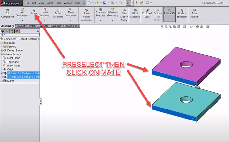
So far we have accessed the main tools by going to the Assembly tab in the CommandManager and clicking the Mate command. However, SOLIDWORKS has given us other options for quickly accessing the Mate command, or using it more effectively.
We can preselect faces, edges, or vertices before clicking Mate. Using the CTRL key and our left mouse button, we can select two planar faces on separate components. After clicking the Mate button, our selections will already be added into the blue box and SOLIDWORKS will pick the most appropriate Mate type.
For example, if we select two cylindrical faces, SOLIDWORKS will automatically pick Concentric. If we select four faces, SOLIDWORKS will automatically pick Width since this is the only Mate type that uses four faces.
We can take this a step further by using the box that pops up next to our cursor after releasing the CTRL key and have selected the second part.
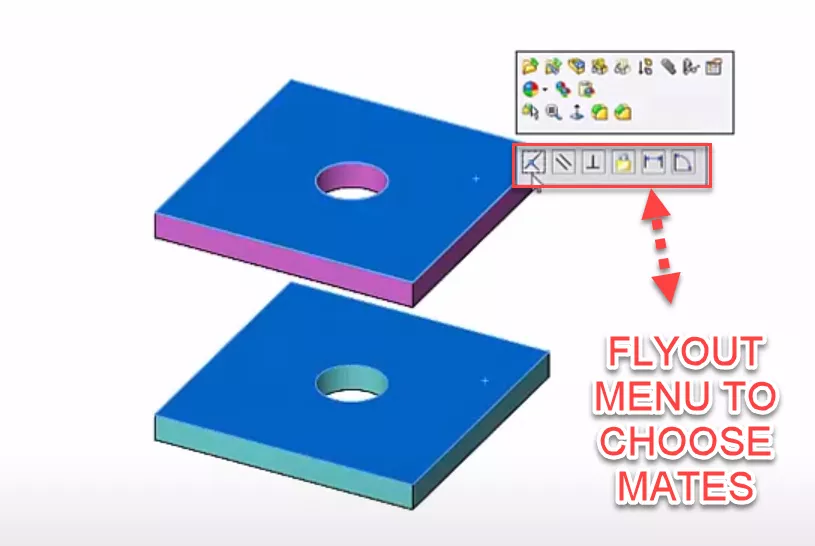
The flyout menu allows you to quickly create a Mate without activating the Mate tool. Notice there are buttons for all the applicable Standard types.
This only allows for a singular Mate as it does not open the Mate dialogue box.
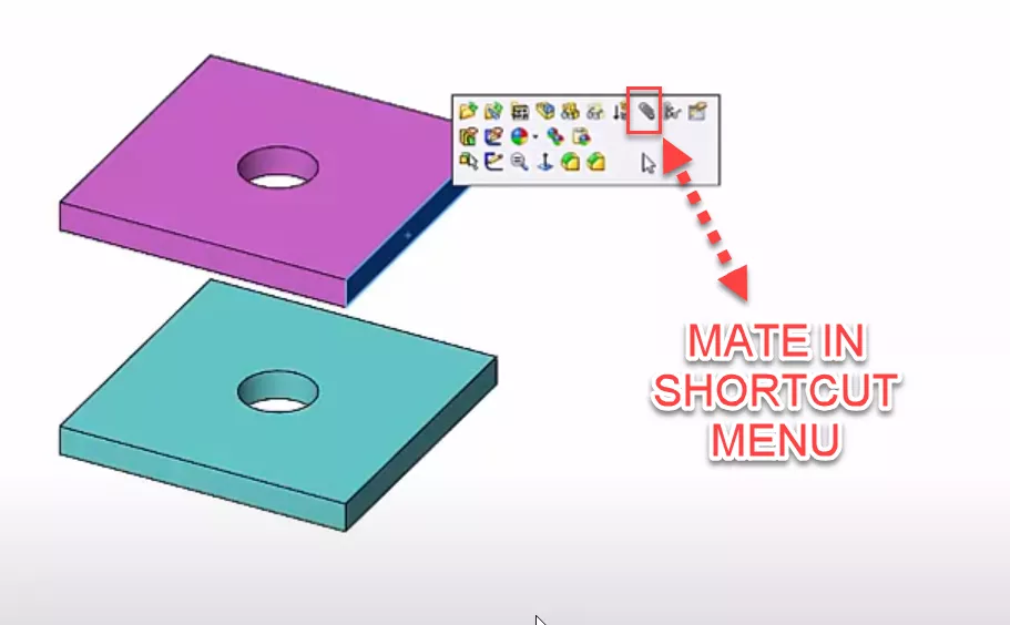
Another way is to click first face edge or vertex and then immediately stop moving the mouse. A context menu pops up the options but it fades if you move your mouse.
We can reactivate it by clicking on our selection again. One of the options on this menu is the Mate paper clip. This will take us right into the Mate dialogue without even having to move our cursor outside the graphics area. Here we can select the other face for faces without having to hold CTRL.
The same menu pops up if you right-click on a component but there's also a long list of options that move the Mate button farther away from your cursor if you want to go even faster, you can use the ‘S’ shortcut key or as a mouse gesture.
SOLIDWORKS Training
If you would like to master the powerful tools found within SOLIDWORKS, see our available Self-Paced Training Courses.

SOLIDWORKS CAD Cheat Sheet
Our SOLIDWORKS CAD Cheat Sheet, featuring over 90 tips and tricks, will help speed up your process.
More SOLIDWORKS Tutorials
How to Mirror Parts in SOLIDWORKS Two Different Ways
Using Cosmetic Threads: SOLIDWORKS Best Practices
SOLIDWORKS Wrap Feature Tutorial
Exporting Curved Surfaces in SOLIDWORKS to a DWG/DXF in 2 Steps
Creating Reference Planes in SOLIDWORKS: Offset, Angle, Mid, & Cylindrical Surface

About Matthew Kusz
Matthew Kusz is a Senior Technical Support Engineer at GoEngineer. When Matthew isn’t assisting customers with their engineering challenges, he spends his free time repairing antique watches/clocks, designing furniture, tending his aquariums and learning about bee keeping.
Get our wide array of technical resources delivered right to your inbox.
Unsubscribe at any time.