SOLIDWORKS Rack and Pinion Mate Tutorial
SOLIDWORKS assemblies let you choose from four categories of Mates: Standard, Advanced, Analysis, and Mechanical. (New to SOLIDWORKS Mates? Check out our article Introduction to SOLIDWORKS Mates for more details)
How to Use Rack and Pinion Mate in SOLIDWORKS
Mechanical Mates allow us to create a Rack and Pinion Mate that creates a standard rack and pinion relationship between—you guessed it—a rack gear and a pinion (or spur) gear. When this Mate is applied, rotational movement of the pinion causes linear motion of rack and vice versa.
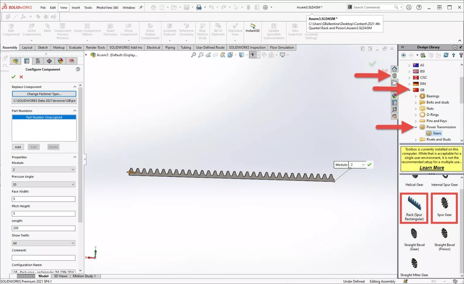
Inserting Gears
Gears are found in the Toolbox under GB > Power Transmission > Gears. The appropriate gears can be dragged into an assembly and relevant specifications such as pitch and pressure angle can be selected from the PropertyManager after dropping them into the graphics area.
Locating the Gears
Before adding the Rack and Pinion Mate we need to locate the gears. I created a Coincident Mate between the sides of the gears, and then a Distance Mate between the axis of the pinion gear and the pitch line of the rack gear. I also placed the teeth so that they do not overlap.
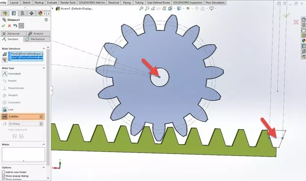
To make the pitch of the rack gear selectable, I made the sketch for the tooth visible in the FeatureManager Design Tree.

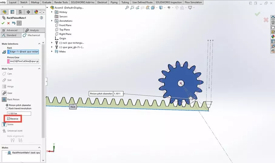
Adding the Rack and Pinion Mate
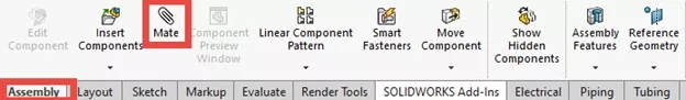
The Rack and Pinion Mate is found within the regular Mate tool in the Assembly tab of the CommandManager.
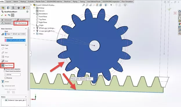
Simply select Mechanical Mates, Rack and Pinion, and then select the gears. To select the rack, click on the bottom edge of the rack gear. To select the pinion, select its pitch line. The rest of the fields auto-populate.
Click the green check and test it out! By dragging one of the gears with the mouse, the other should move accordingly. If the movement is backwards, just edit the mate and check the Reverse box.
Tip: If one of the gears moves but the other doesn’t, it might be fixed in place. Right-click on it in the FeatureManager Design Tree and select Float.
Interested in learning more tips and tricks to get the most out of your SOLIDWORKS? Check out our YouTube channel or the tutorials listed below.
More SOLIDWORKS Tutorials
Introduction to SOLIDWORKS Mates: Standard, Advanced, & Mechanical
Exporting Curved Surfaces in SOLIDWORKS to a DWG/DXF in 2 Steps
SOLIDWORKS Calculating Volume of a Solid
Creating Reference Planes in SOLIDWORKS: Offset, Angle, Mid, & Cylindrical Surface

About Gary Ballentine
Gary Ballentine is a Mechanical Engineer based out of our Headquarters in Salt Lake City, Utah. He earned a Bachelor’s degree from the University of California, Davis, a certification in Technical Writing from San Francisco State University, and a Bachelor’s degree in Mechanical Engineering from the University of Utah. Gary has been part of the GoEngineer family since April 2019 as a Support Engineer and Certified SOLIDWORKS Instructor.
Get our wide array of technical resources delivered right to your inbox.
Unsubscribe at any time.