Modify an Imported Body in SOLIDWORKS
In this quick tip, learn how to modify an imported body in SOLIDWORKS without needing to reverse engineer the Part file into SOLIDWORKS Features.
Imported Vendor Files
In this example, a vendor supplied a version of a desired part. It was imported as an IGES file. We want to modify this part without remodeling it from scratch. To do so, we will create a version of the model that matches the specifications of the new part directly from the existing geometry.
Open the Vendor File
Below is the file we will start from. The red arrow is pointing to a tab that needs to be flipped vertically in the +Y axis. The tab needs to be extended 0.75” in the +Z direction to match the new part. (Figure 1)
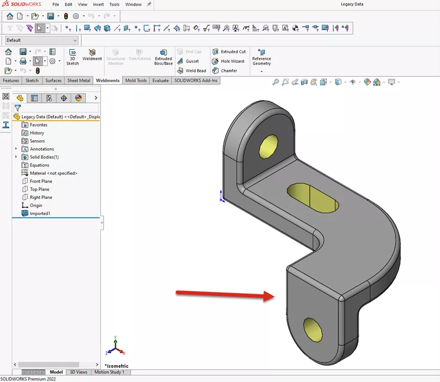
Figure 1: Stock imported part file from the vendor
Split the part into multiple bodies
To begin modifying the part, we need to create a cut through the part.
First, add a reference plane (Figure 2) parallel to the outer face of the tab (highlighted) and coincident it with the vertex or tangent edge of the part.
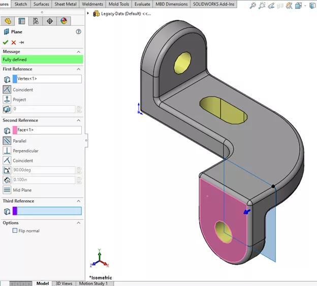
Figure 2: Create a Reference Plane through the part
Next, use the Split Feature (Figures 3 and 4) to separate the single body into two separate bodies. The reference plane we generated in the previous step is used as the cutting plane for the Split Feature. And, as you can see, the single part has been split into two bodies. (Figure 5)
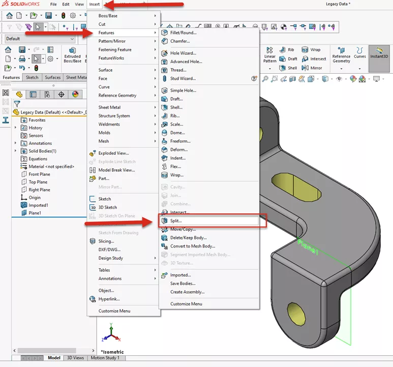
Figure 3: The Split feature is found under Insert > Features > Split
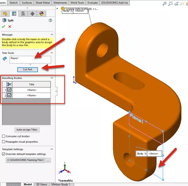
Figure 4: Select the cutting plane and click ‘Cut Part’ to divide the part into two bodies
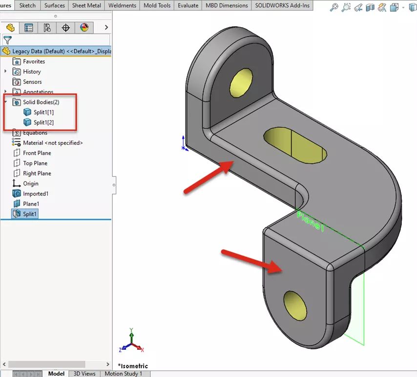
Figure 5: The Split Feature has created two separate bodies
Reorient the bodies
Now that the part has been split into two bodies, the next step is to reorient the body into the desired location. To do so, use the Move/Copy Command via Insert > Features > Move/Copy (Figure 6).
-
Suggested Reading >> Using the Move/Copy Body Feature in SOLIDWORKS
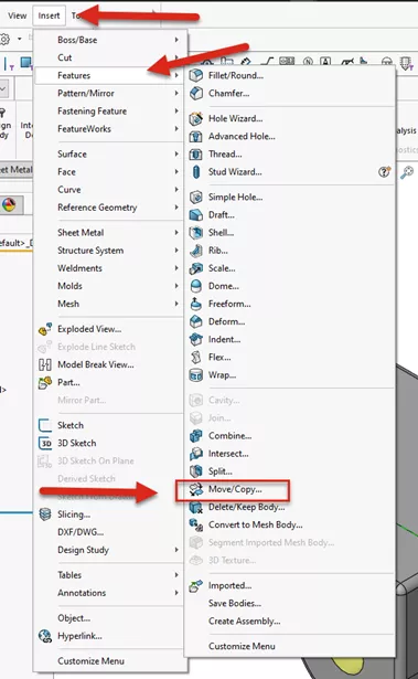
Figure 6: Move/Copy Feature location
Think of the Move/Copy Feature as you would Assembly Mates, but for use in Multibody Parts.
Start by selecting the body to be moved. (Highlighted in Figure 7) Select the two faces for a Coincident Mate. Right-click on the top face of the second body, use Select Other and pick the bottom face of the part. (If the bodies aren’t oriented as desired, use the Mate Alignment option to flip the orientation of the body). Click Add to create additional mates (do not click “OK” to close the Feature at this time).
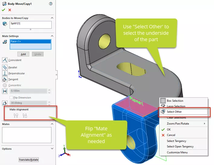
Figure 7: Adding the first Mate to orient the solid bodies
Now that the body is oriented correctly in the +Y axis, add a distance mate between the faces of the bodies. (Figure 8) The desired distance is 0.75”. Click Add to add one more mate to the Feature.
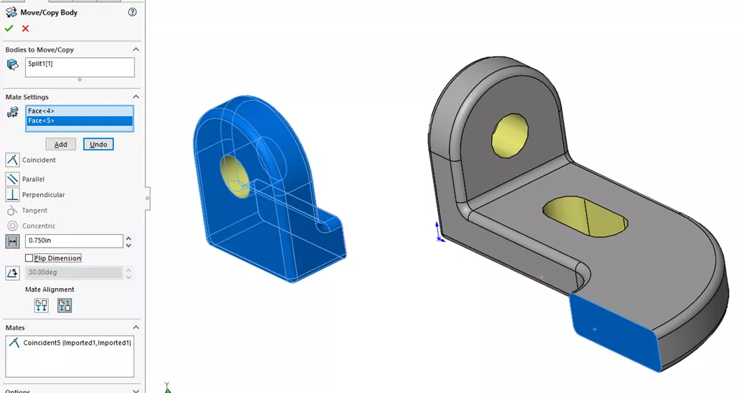
Figure 8: Use a Distance Mate to locate the Solid Body 0.75” in the Z axis
The final step in the Move/Copy Feature will be to add a Coincident Mate between the Tangent edge or the curved body and the outer flat face of the second body. (Figure 9) Click OK when ready.
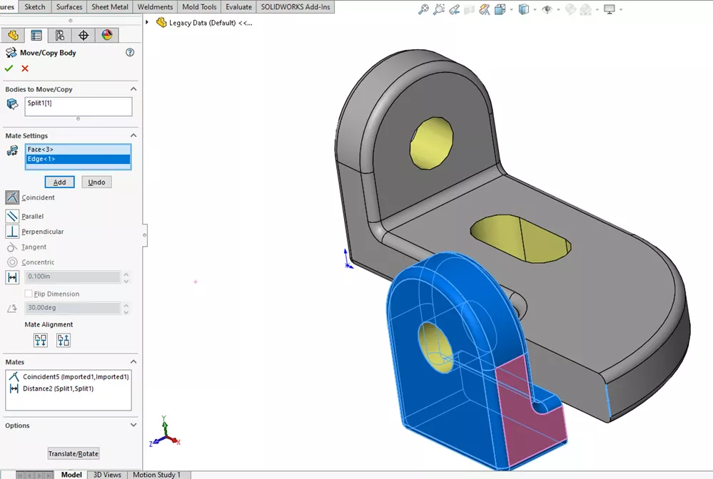
Figure 9: Adding a Coincident mate between the two bodies for final positioning
Converting a multibody part back into one solid body
Now that the two bodies are in the correct orientation and locations, we need to fill in the space left between them in order have one solid body again. (Figure 10) To do so, we'll use a simple Boss-Extrude Feature.
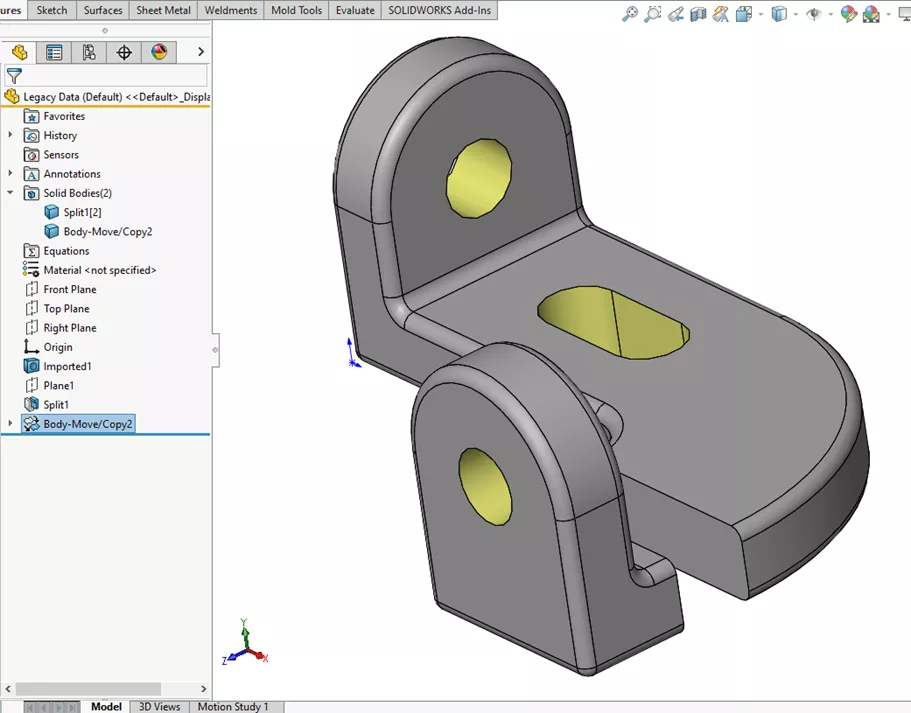
Figure 10: Multibody part to be rejoined as a single body
The Convert Entities tool in the CommandManager Sketch tab is used to create a sketch on one of the faces. (Figure 11)
The Convert Entities command creates a sketch on the edges of the part with On Edge Sketch Relations already in place, fully defining the sketch.
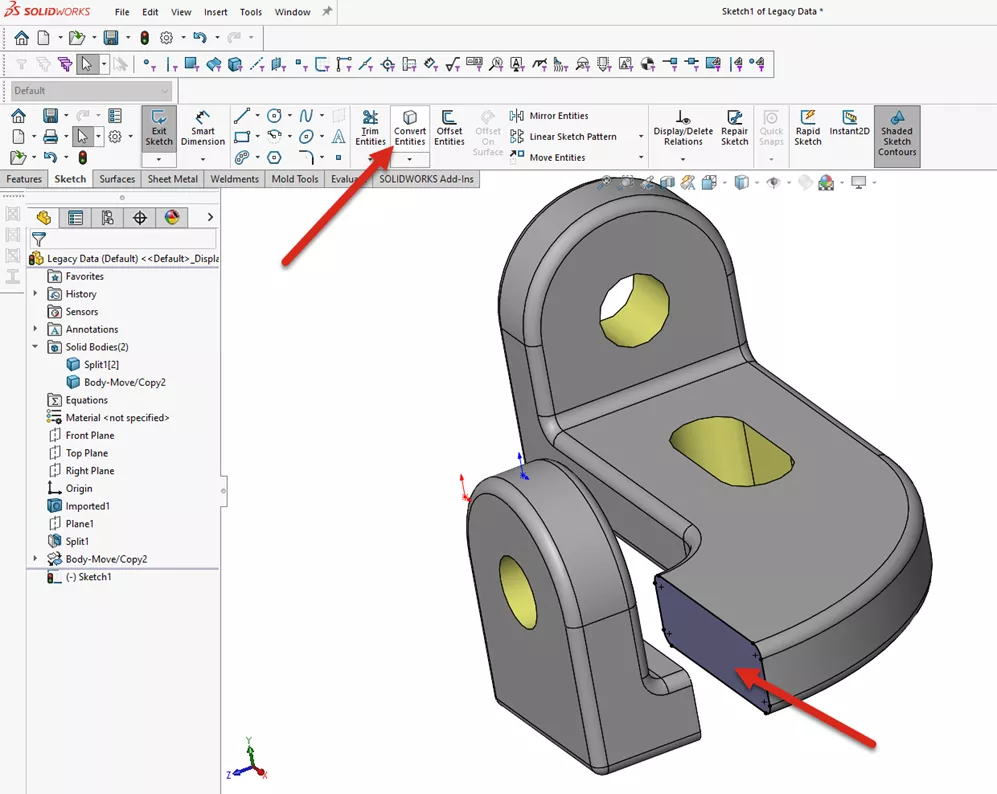
Figure 11: Sketch > Convert Entities
Use a Boss-Extrude Feature, using the new sketch created in Figure 11. Change the End Condition to Up to Surface and select the mating face of the second body (Figure 12).
Note that the Merge Result checkbox should be selected at this time.
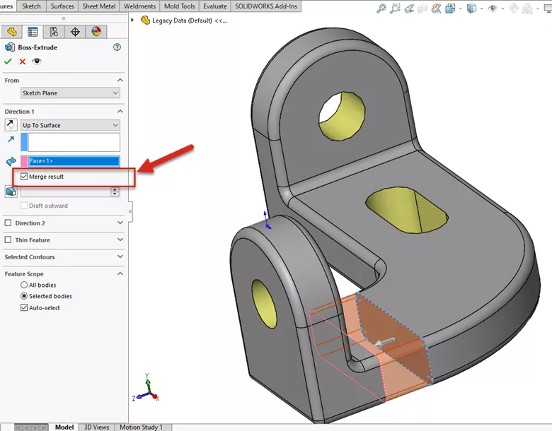
Figure 12: Use the Boss-Extrude feature and Up to Surface command to bridge the gap between the bodies
Finished modified part file
And as shown in Figure 13, with a few simple steps, the part has been modified without needing to convert the imported solid body into SOLIDWORKS Features.
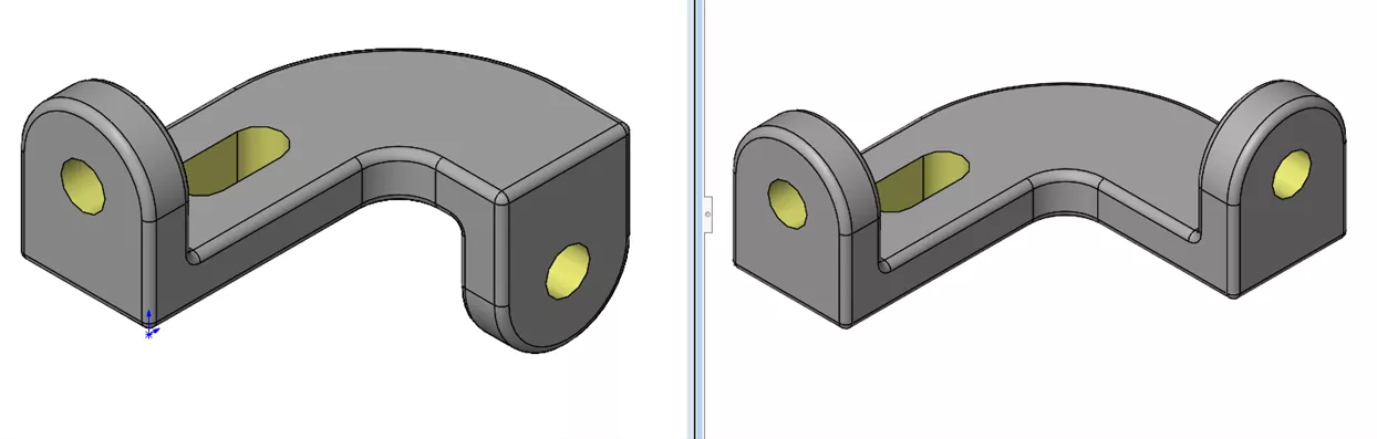
Figure 13: Before (left) and after (right)
I hope you found this tutorial helpful. Check out more SOLIDWORKS tips and tricks listed below.
More SOLIDWORKS Tutorials
How to Create a Lip/Groove Feature in SOLIDWORKS
How to Use SOLIDWORKS Feature Freeze
SOLIDWORKS Mold Tools: Split Line & Parting Line Explained
Create a SOLIDWORKS Assembly from a Multibody Part
![]()
About GoEngineer
GoEngineer delivers software, technology, and expertise that enable companies to unlock design innovation and deliver better products faster. With more than 40 years of experience and tens of thousands of customers in high tech, medical, machine design, energy and other industries, GoEngineer provides best-in-class design solutions from SOLIDWORKS CAD, Stratasys 3D printing, Creaform & Artec 3D scanning, CAMWorks, PLM, and more
Get our wide array of technical resources delivered right to your inbox.
Unsubscribe at any time.