SOLIDWORKS CAM Tab Cutting Guide
Tab cutting in computer-aided manufacturing is a way to give special attention to components being manufactured. You can set material to not be removed from your stock so when your laser, waterjet, or plasma cutter is removing material, inside core material will not tip or fall damaging the cutting tool, machining center, or part. An example of using tab cutting would be when producing a part such as the top panel of the machine shown below.
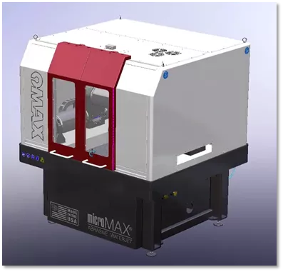
The top panel on this machine has three ports to be cut out. The inside core material could pose a problem if not handled correctly.
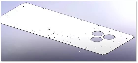
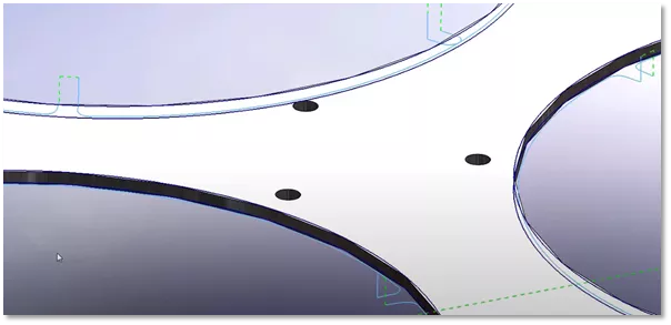
If we were to try and cut those three ports like the following example below, the inside core material could drop or tip, creating a hazard.
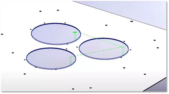
When cutting a port like this, you’d typically need to set up clamps which need to be moved in multiple set ups, expensive vacuum fixtures, or manually creating avoid sketches which take time. SOLIDWORKS CAM includes the option for Tab Cutting which can be accomplished in several mouse clicks.
How to create a Tab Cut
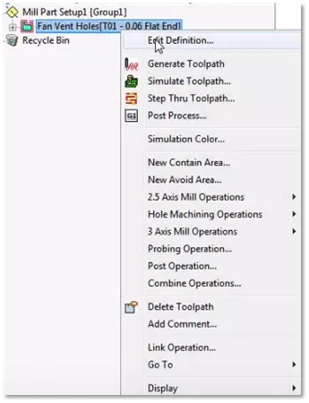
With a contour mill operation already defined, for this example, we can add Tab Cutting by editing the definition of the operation. To do so, right-click and select Edit Definition...
Once you have opened the operation parameters, select the Contour tab, and in the lower right, select the option Tab cutting.
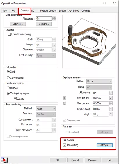
After selecting the Tab Cutting option, click the Settings button. The Tab Cutting settings dialogue will launch. Here we can choose how we’d like our tabs to be generated.
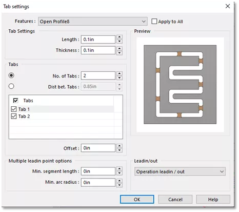
SOLIDWORKS CAM Tab Settings Options
Let's go over some of the options we have in this dialogue.
- Length and Thickness: This option controls the length and overall thickness of the tab when depth of cut is important. This gives you control over rigidity of the core material, which is attached to the main plate.
- No. of Tabs: This option controls the number of tabs applied to the feature.
- Dist bet. Tabs: Controls the distance between tabs and is used as an alternative to number of tabs. Set the distance and it will fill the number of tabs for the offset.
- Tabs: Select individual tabs to change the center-to-center offset. This option lets you adjust the position of each tab to desired.
- Multiple Lead-in points options: This option gives us more real estate for our lead in lead out to prevent witness marks left over from the tool plunging at the finished size.
- Lead-in/ out: Offers further refinement based on the type of cutting tool used, material type, and rigidity. Available options to use are operation lead-in/ out, Feed over, and retract to clearance plane.
Below is an example of the visual display when applying the number of tabs.
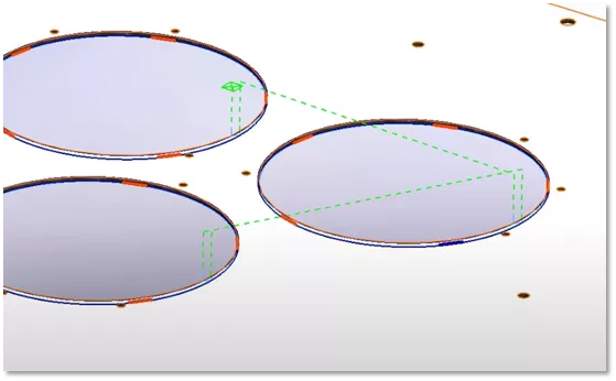
When applied with the default settings, Multiple Lead-in/out will apply the following to the tool path.
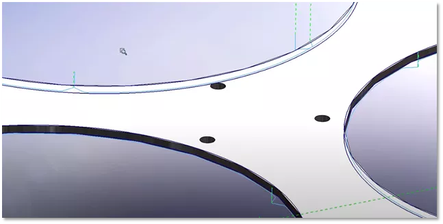
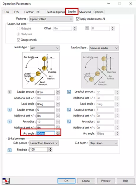
The default settings may not work for you. These settings are controlled by the lead-in tab within the operation parameters. For this example, we can set the Arc Angle from 45 degrees to 90 degrees.
You will get the resulting modification to the tool path leaving a nice section of tab for your core material to remain rigid.
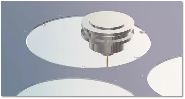
Once you are happy with the tab that you have defined, you can simulate the toolpath to review the validity of the path. This process can help show the cutting that will take place and give us confidence in our manufacturing set up.
Tab Cutting for SOLIDWORKS CAM can allow you to save time and reduce costly mistakes by simplifying core material removal during the machining process.
Learn More About SOLIDWORKS CAM
SOLIDWORKS CAM Features & Allowable Operations
SOLIDWORKS CAM and CAMWorks CommandManager Icon Reset
SOLIDWORKS CAM Overview: Standard vs. Professional
SOLIDWORKS CAM / CAMWorks 3-Axis Operations
![]()
About Nick Stanley
Nick Stanley is a SOLIDWORKS Technical Support Specialist at GoEngineer.
Get our wide array of technical resources delivered right to your inbox.
Unsubscribe at any time.