SOLIDWORKS Design Tables Made Easy
SOLIDWORKS Design Tables allow you to quickly build and manipulate Part and Assembly Feature parameters in different configurations using an embedded Microsoft Excel worksheet.
Note: To use Design Tables, you must have Microsoft Excel installed on your computer.
Part Control: Dimensions, Feature dimensions and suppression state, Equations, Sketch Relations, materials, and custom properties.
Assembly Control: Component suppression state and fixed/floating state, Assembly Feature dimensions and suppression state, Hole Wizard size, Mates, Equations, Sketch relations, Display States.
In the following simple example, the design parameters are already in place as part of the design criteria sent from someone else. It's not required to have every bit of criteria in advance; the Design Table allows for adding and/or modifying more information later.
Designing a set of Allen Wrenches
For this exercise, several extremely similar components are required in an Assembly. I could take the time to save multiple Part files; adjusting dimensions as needed, and saving each with a unique filename, or, I can capture all the wrenches in one single Part file with multiple Configurations, each named with a different part number, and organized via Design Table.
Keeping track of one Part file is certainly more convenient. However, this comes with a caveat: A design table creates multiple configurations, and that can lead to an increase in file size resulting in performance issues.
Design Criteria
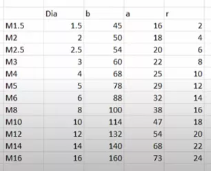
I’ll start a part with the first set of parameters above for the M1.5.
I created two sketches so that I can use the Swept Boss/Base feature.
Fully define each sketch and add names for the dimensions related to the column headers above by double-clicking the dimension and changing D1@Sketch4 to r@Sketch4.
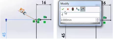
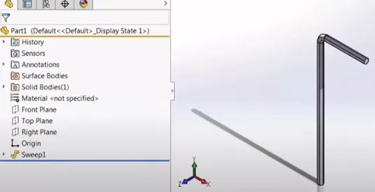
I'll use the two sketches, both having named dimensions from the criteria, to create the Sweep.
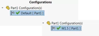
Configurations
The first Configuration is always Default, but we know that the first configuration is actually M1.5 from the criteria, so rename it to M1.5.
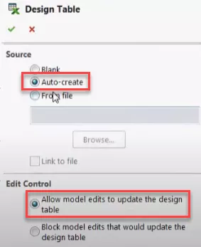
With M1.5 as our baseline, we’ll insert a Design Table:
From the drop-down, Insert > Tables > Design Table.
I’ll leave it set to auto-create and allow model edits to update the Design Table. Doing so will allow the Design Table to update with model edits.
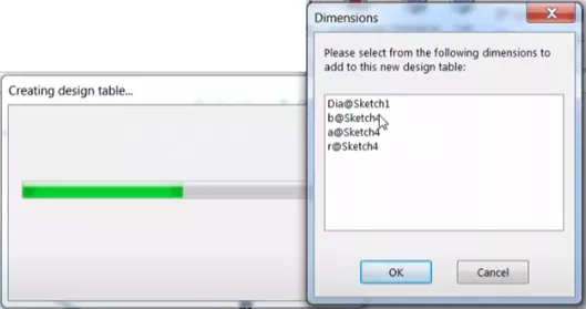
After selecting the green checkmark to accept, it will auto-generate the design table and ask what to include. I will SHIFT select all the dimensions listed.
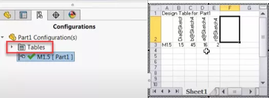
This results in the table shown on screen and a Tables flyout in the Configuration tree.
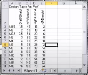
At this point, I can add the criteria to the Design Table. In this case, because it was already in a worksheet, I can simply copy and paste the needed cells from one table to the one above.
After double-checking the Design Table, I can click outside the table in the graphics area, and SOLIDWORKS will ask me to confirm the configurations generated in the Design Table.
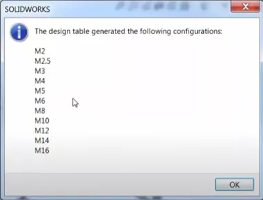
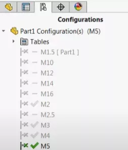
Select OK, and the new configurations are shown in the tree. Notice the Excell “x” next to their names indicating that they are managed with the Design Table.
Making changes
Since we didn't use material from the beginning and before all of the design criteria was developed, we can go back and edit the Design Table to include the new criteria or change any of the parameters that have been entered.
If I add a material type to a Configuration, then enter the Configuration tab and edit the Design Table by right-clicking, it will notice that I have added the material and ask me if I want to add the new parameter to the Design Table.
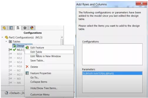
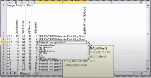
Select OK to add and it adds that column “F” to the Design Table.
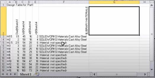
This new column allows us to change the material from within the Design Table drop-down.
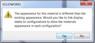
SOLIDWORKS will then ask if you’d like to link the display states to the different materials.
(Yes, is good)
In closing, I’d like to emphasize that it’s a good idea to double-check each configuration and keep configurations to a minimum. Hit Save and you're done.
SOLIDWORKS Drawings Training
Learn how to create drawings of SOLIDWORKS Parts and Assemblies and master SOLIDWORKS Tables in the SOLIDWORKS Drawings professional training course offered by GoEngineer. Learn more below.

I hope you found this tutorial helpful. Check out more SOLIDWORKS tips and tricks listed below.
More SOLIDWORKS Tutorials
Office 365 Excel Design Tables in SOLIDWORKS
How to Scale a Part in SOLIDWORKS 2 Different Ways
Easily Save SOLIDWORKS Configurations as Separate Parts
How to Repair Broken References in SOLIDWORKS

About Randle Wood
Randle is a Technical Support & New Products Specialist and has been with GoEngineer since 2009. He has a Bachelors of Science in Industrial Design and has been a SOLIDWORKS user since before the turn of the century.
Get our wide array of technical resources delivered right to your inbox.
Unsubscribe at any time.