SOLIDWORKS Direct Editing Tools: Move Face & Delete Face
In SOLIDWORKS, Direct Editing tools provide the flexibility to modify geometry that does not contain model features, such as an imported STEP, Parasolid, or IGES file. In this guide, we will look at some Direct Editing tools such as Move and Delete Face.
Turn on Direct Editing in SOLIDWORKS
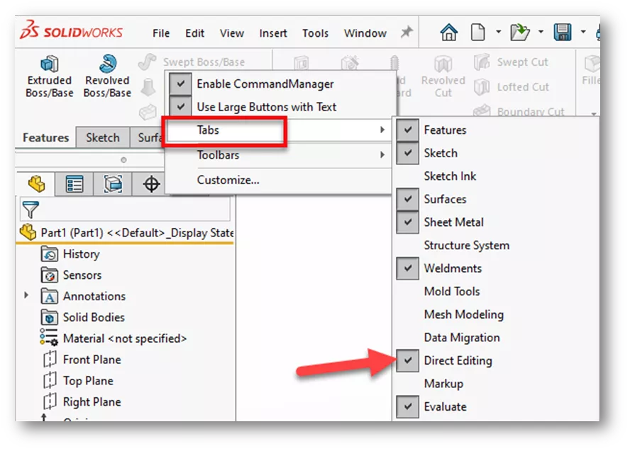
To turn on the Direct Editing tab, right-click anywhere on the CommandManager, go to Tabs, then select Direct Editing.
Move Face
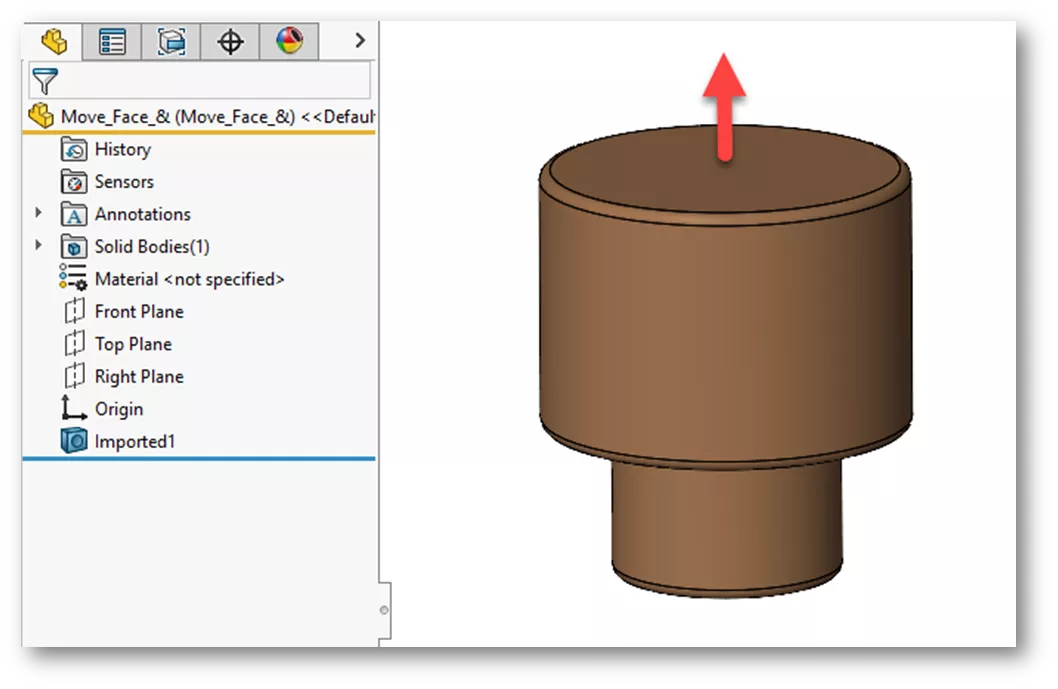
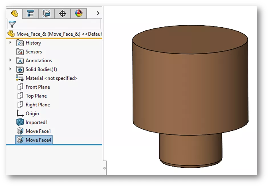
In the example below, we have an imported Parasolid with no features to edit. We need to lengthen the body in the Y-direction by 5mm. We can use the Move Face command to accomplish this.
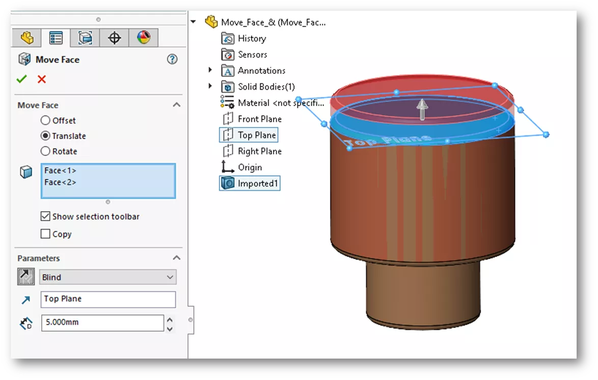
On the Direct Editing tab, choose Move Face, then select Translate. For the faces to select, here we'll choose the bottom and filleted face of the base. Under Parameters, choose a Blind end condition, select the top plane for the direction reference, then key in 5mm for length and click OK.
Now, we need to increase the diameter of the base just a bit. We can also use Move Face to accomplish this. For this example, we will use the Offset option.Select the cylindrical face, key in a length of 3mm and click OK.
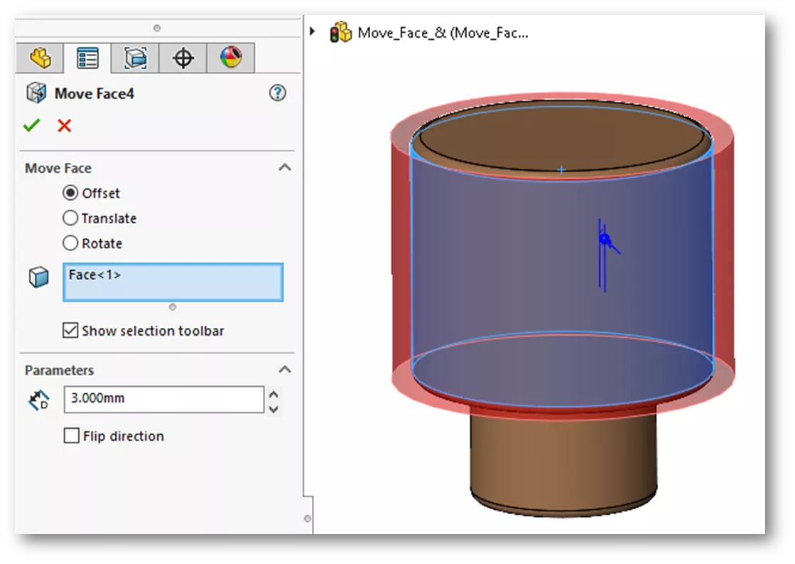
This process removes the fillets from the cylinder edges. We can add fillets or chamfers back in later.
Delete Face
Suppose we want to remove the remaining fillet and add chamfers to the edges. To remove the fillet, use the Delete Face command on the Directing Editing tab. Under Selections, choose the fillet face. Under Options, select Delete and Patch and click OK.
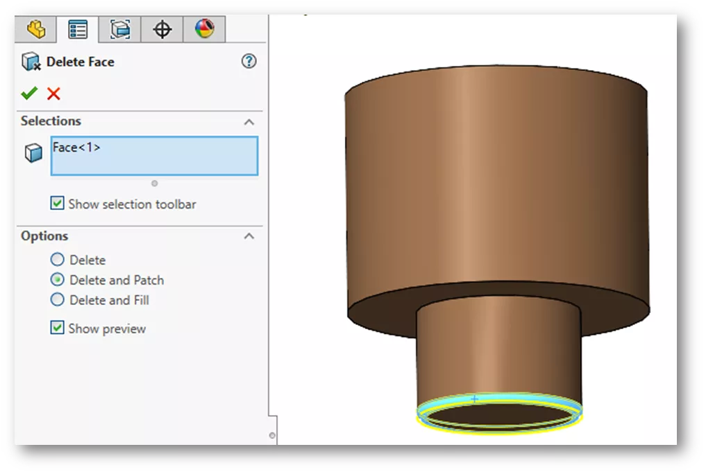
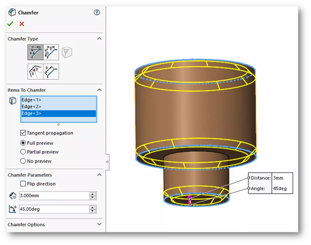
The Delete and Patch option resulted in the filleted face being removed and the edges brought together. The Chamfer command is also on the Directing Editing tab. We’ll engage the command and select the edges, key in a value of 3mm, and click OK.
We have now completed our design changes using Direct Editing tools in SOLIDWORKS. I hope you found this tutorial helpful. Check out more tips and tricks listed below. Additionally, join the GoEngineer Community to participate in the conversation, create forum posts, and answer questions from other SOLIDWORKS users.
Learn more about Direct Editing tools, advanced part modeling, and assembly modeling capabilities by enrolling in the SOLIDWORKS Advanced Bundle training course. Both online and in-person classes are available.

SOLIDWORKS CAD Cheat Sheet
SHORTCUTS ⋅ MOUSE GESTURES ⋅ HOT KEYS
Our SOLIDWORKS CAD Cheat Sheet, featuring over 90 tips and tricks, will help speed up your process.
More SOLIDWORKS Tutorials
SOLIDWORKS Autotrace Tool Tutorial
3 SOLIDWORKS Surfacing Tools to Try
Using the Move/Copy Body Feature in SOLIDWORKS
Why SOLIDWORKS Mates Can Cause Slow Assemblies

About Zach Brown
Zach Brown is a certified SOLIDWORKS Expert and a Technical Support Engineer. Prior to working at GoEngineer, he spent 15 years as a mechanical designer, CAD support tech, and instructor using SOLIDWORKS. His hobbies include playing guitar, riding motorcycles, and skiing.
Get our wide array of technical resources delivered right to your inbox.
Unsubscribe at any time.