SOLIDWORKS Electrical Custom Duct or DIN Rail Creation
The article describes how to create a custom duct or DIN rail to be utilized in SOLIDWORKS Electrical 3D with adjustable length and hole patterns for panel cutouts.
Making the body
There is a sample duct assembly in the SOLIDWORKS Electrical software found in the SOLIDWORKS Electrical data folder under SOLIDWORKS > sldPrt named EW_DUCT_H1.SLDASM. We could make a copy of this part and customize it as required, but instead, we'll create one from scratch.
Create a part in SOLIDWORKS and Save As the desired part name.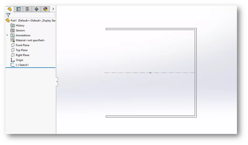
Once the sketch is created and saved, right-click it and use Rename tree item to change the name of the sketch to EW_SKETCH. Save the part.
Extrude the sketch to a length of 500 mm. Complete the Extrude Feature. Rename the Extrude Feature as EW_Extrude via Rename tree item in the right-click menu. Save the part.
Making a pattern
Some ducts have slots that need to be added.
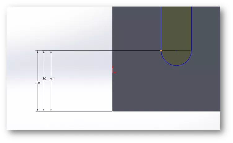
Create a sketch for the slot cutout and extrude cut.
Note: Keep in mind design intent! When wanting the cut of the slot to be able to adjust depending on the depth of your duct, dimension from the base side of the part. Utilizing this type of dimensioning will allow the slot to always be positioned correctly when the size of the duct adjusts with the Electrical Manufacturer Part.
A pattern of the slot can be made once the Extrude cut is completed and the part is saved. Under the Features tab, select Linear Pattern. Along with the selection shown below, Up to reference will allow for the correct spacing as the length of the duct changes. Do not use instance numbers because this will deform the part when the Electrical software changes the length, height, and depth.
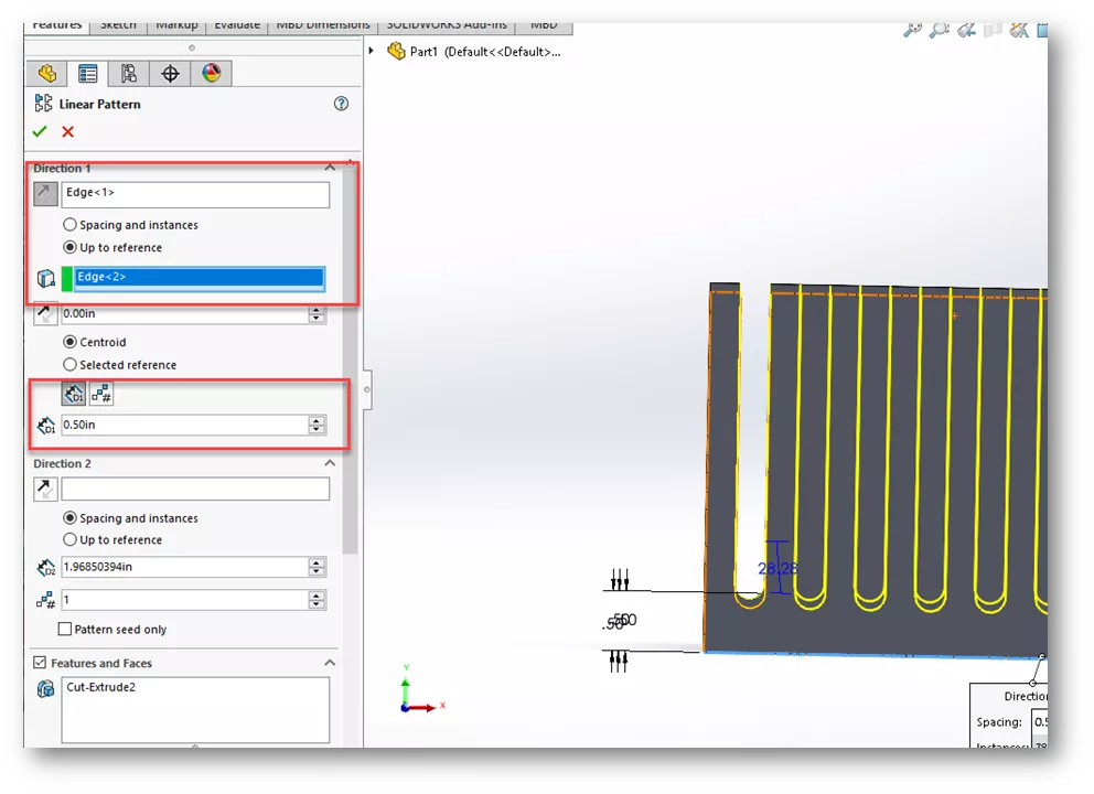
When making this pattern, the Up to reference option will be the end of the duct (Edge 2) while using a distance away from the original pattern of 0.5 inches. Finish the part and Save!
Making a configuration
In order to make this part work with the SOLIDWORKS Electrical software and have an adjustable length when placing, a configuration needs to be used.
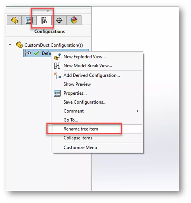
First, rename the default configuration to “EW_CONFIG”.
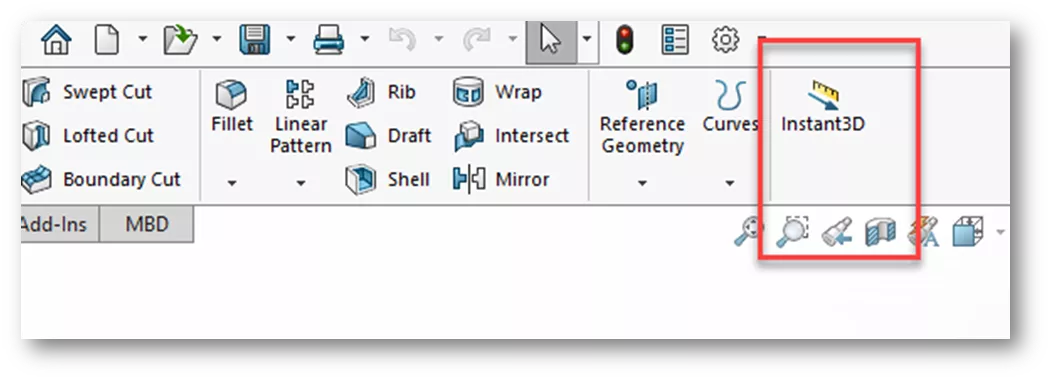
Once the default configuration is renamed, ensure that Instant3D is turned off.
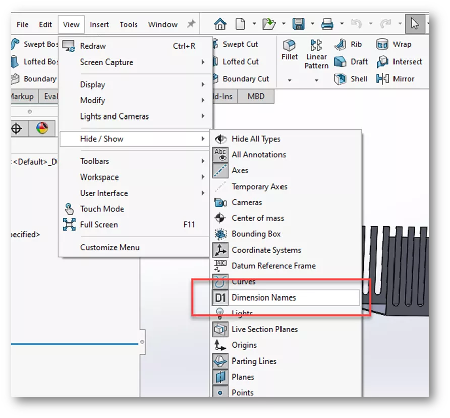
Additionally, you will want to turn on the Dimension names from the View tab > Hide/Show > Dimension Names.
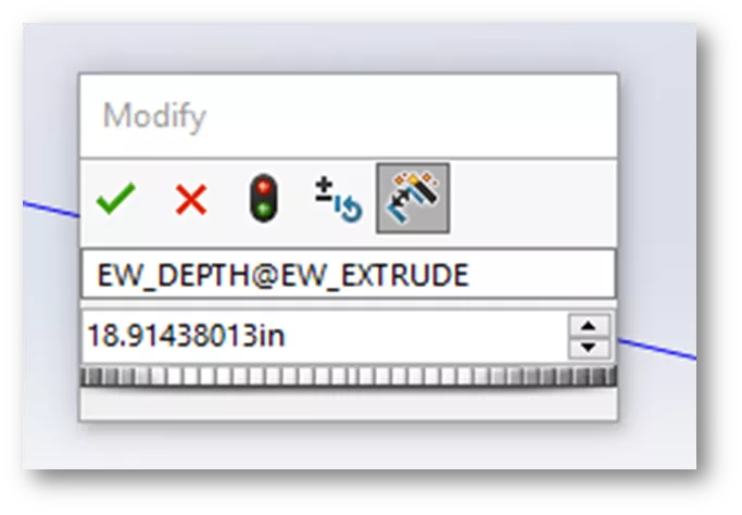
Doing this will allow for ease of working with the dimensions and renaming or changing them on the fly. In this example, we will rename the dimension for the depth, called D1.
Rename the depth dimension. Renaming will then allow the SOLIDWORKS Electrical software to drive the length of the part and adjust with the slide or with an input. To make this name change, double-click on the extrude of the part (the dimensions will then appear). Double-click on the length or D1 dimension in your graphics area. In the upper line of the dialog box, change the name from D1 to EW_DEPTH. It should then fill in the rest for you when you select the green check to appear as shown below. The actual dimension does not matter at this time, it is adjustable and will be defined when utilized. Save your part.
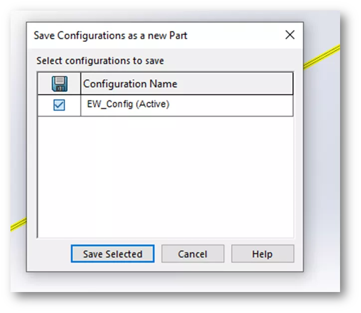
Double-click on the EW_Extrude again, with the dialog open, proceed to the Configuration tab on the left side browser. Highlight the configuration name on the left, right-click, and select Save Configuration. This will display another dialog. Ensure the configuration is checked and active. Select Save Selected. If prompted to save the part over the existing file, go ahead and overwrite.
There should now be two blue dots (one at each end of the part). These blue dots indicate that the part is good. Close the dimension tool in the left browser if it is open.
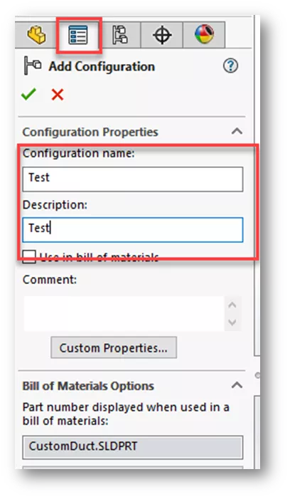
In order for the duct or DIN rail to behave properly in an electrical assembly for updating the length, a secondary configuration is required. Select the Configuration tab, highlight the name of the part, and right-click. Select Add Configuration. Select a name and description and close the command by selecting the green checkmark.
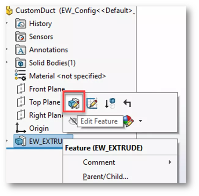
On the Configuration tab, double-click the EW_CONFIG configuration to activate it.
On the FeatureManager Design Tree, highlight the EW_Extrude Feature and edit the Feature.
Change the radio button selection at the bottom of the dialog box to This configuration.
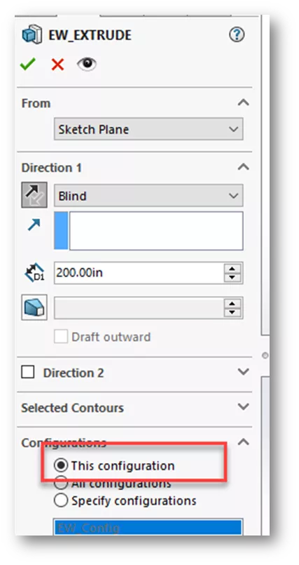
Select the green check mark and save the part!
Add an EW_Path to the Part
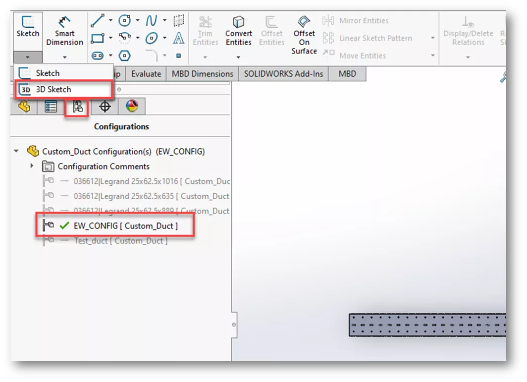
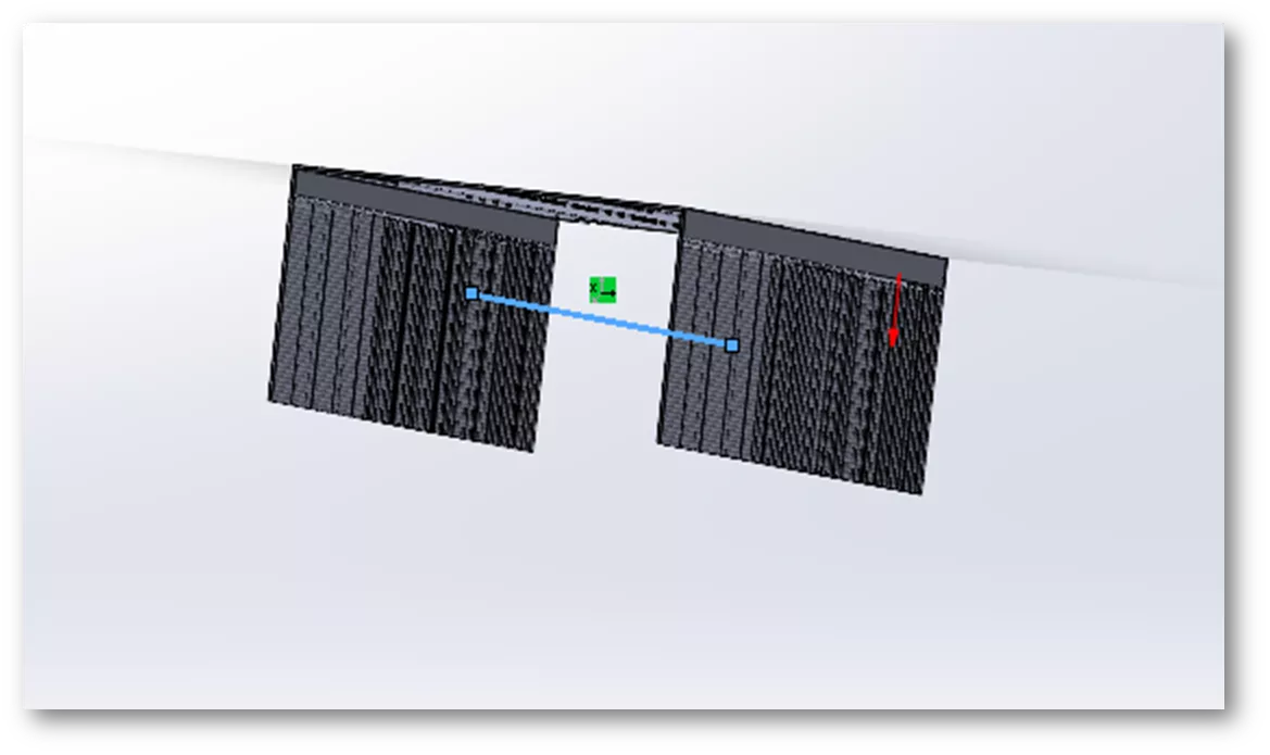
Open the part (if necessary), making sure EW_CONFIG is the active configuration. Using 3D Sketch, draw a line down the center of the length of the duct.
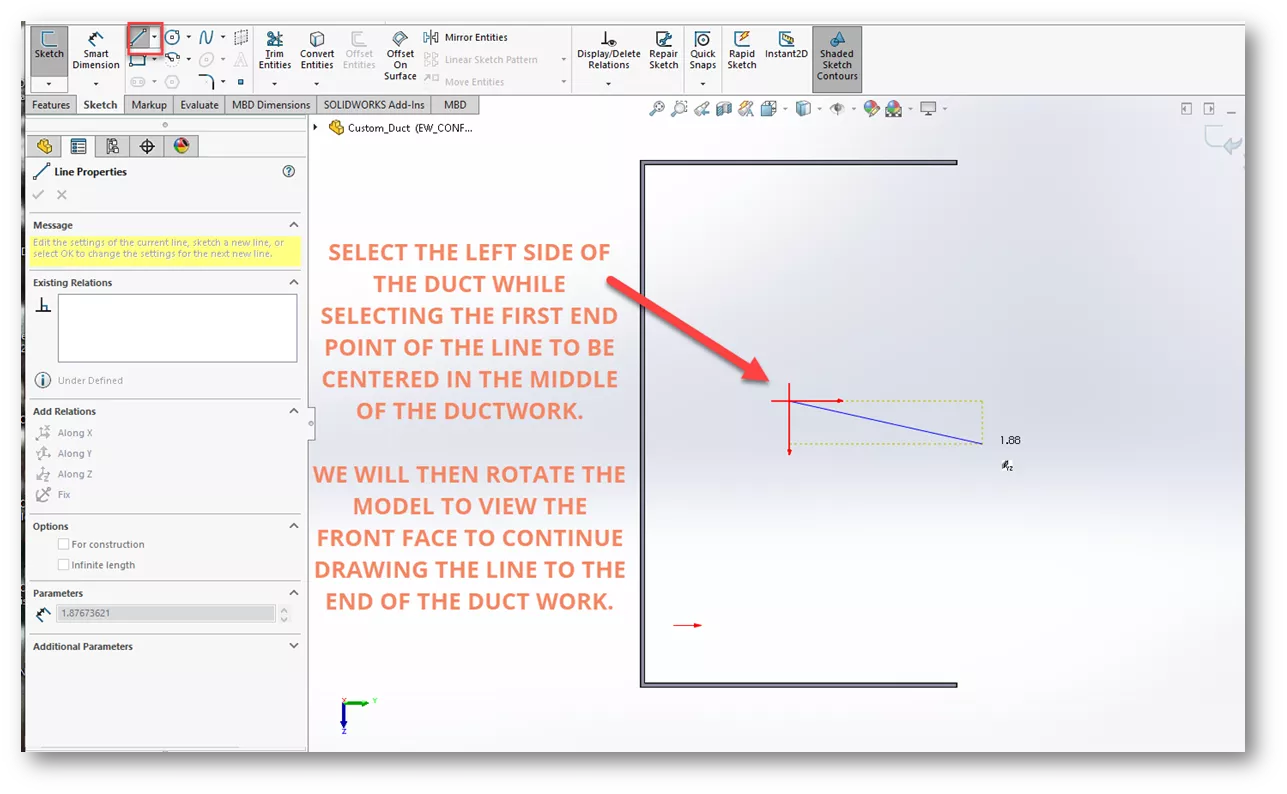
You may need to delete the coincident relations when trying to move the line into the middle of the duct. The two endpoints of your sketch should have on plane relations for the path to be the same as the length of the part when inserted into an assembly. Finish the sketch.
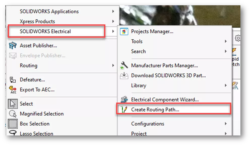
We need to convert the sketch to an EW_Path. If the Electrical 3D tab is missing from the CommandManager, relocate it by going to Tools > SOLIDWORKS Electrical and selecting Create Routing Path...
Select the Convert Sketch radio button. Select the 3D Sketch, then the Green check. The sketch will then turn yellow.
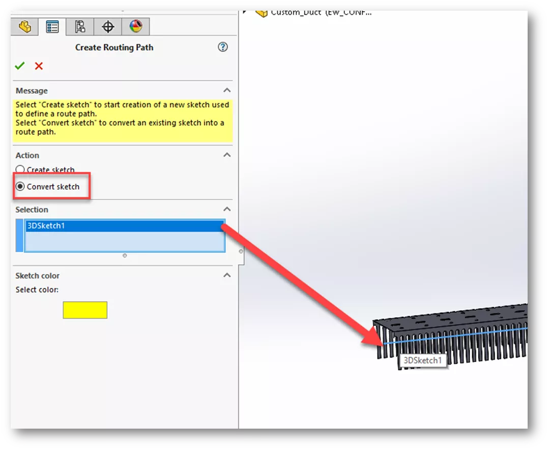
Save the part.
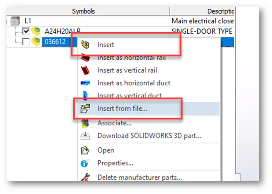
The part is complete! It is now ready for use in SOLIDWORKS Electrical 3D and can be assigned to a specific Manufacturer Part in the Electrical Library. When inserting into an Electrical Assembly, use the Insert command or Insert from File command rather than selecting Insert horizontal or vertical duct or rail.
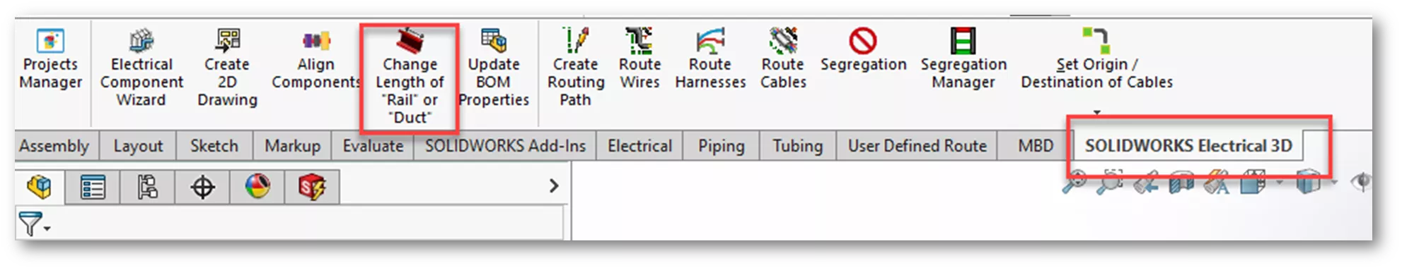
The length of this part can now be modified by using Change length or Rail or Duct from the Electrical 3D options.
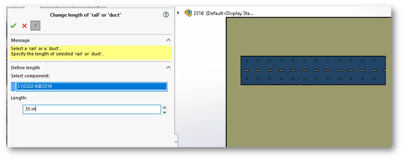
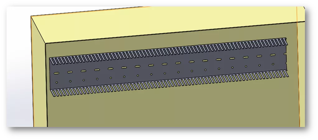
The duct will update the length!
I hope you found this tutorial helpful. Learn more about SOLIDWORKS Electrical below.
Related SOLIDWORKS Electrical Tutorials
How to Create Custom Cables in SOLIDWORKS Electrical
Organize SOLIDWORKS Electrical Projects Using Locations
SOLIDWORKS Electrical vs Routing: Which Product Should I Choose?
SOLIDWORKS Electrical: Wire Mark, Equipotential, and Wire Numbering

About Cheri Guntzviller
Cheri Guntzviller is a Senior Electrical Specialist with over 35 years’ experience. She earned her Bachelor of Science in Electrical Engineering degree from Lawrence Technological University and joined the VAR channel in 2013 with DASI (now GoEngineer). She is a problem solver and is passionate about teaching and helping others solve problems. Based out of Michigan Cheri enjoys gardening, fishing, construction, and spending time with her family and pets. Cheri is a SOLIDWORKS Certified Electrical Specialist, Trainer, and Professional Presenter.
Get our wide array of technical resources delivered right to your inbox.
Unsubscribe at any time.