Organize SOLIDWORKS Electrical Projects Using Locations
In this article, we discuss using locations in SOLIDWORKS Electrical. We'll cover not only what locations are and how to use them, but how they can be used to organize SOLIDWORKS Electrical projects and bring more intelligence into a design to realistically convey as much real-world knowledge of the Electrical system into schematic drawings.
Creating and Using Locations
As we know, getting schematics to 100% detail how the electrical layout and system will be built is just not possible. There can be two components on the same schematic inches apart, but in reality, will be separated by a mile in two completely different buildings connected by a cable that is actually one mile long but only spans two inches on paper.
The solution to display this fact is with locations. In this example project, we don’t have a component separation as large as a mile, but the cable that connects the XLR1 connector to the Boil Kettle; realistically, that cable will be much longer than it looks on the page.
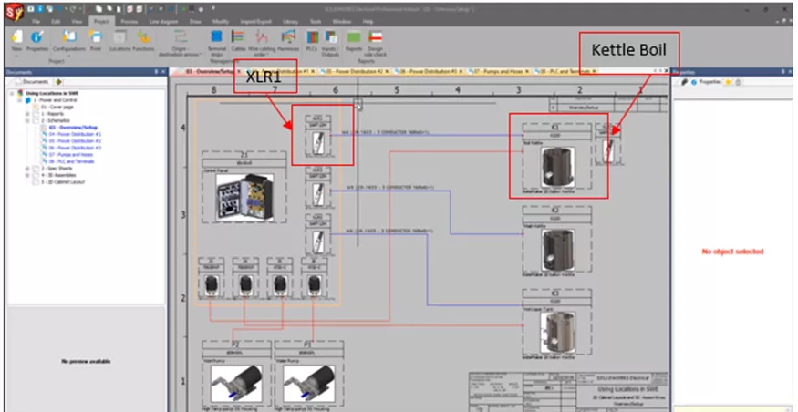
Figure 1: Our Project, XLR1, and Boil Kettle
To show there is some sort of isolation between the two, we can use locations. To do so, go to the Line Diagram tab > Location outline.
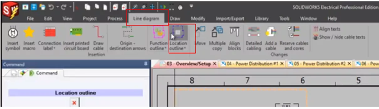
Figure 2: Line Diagram and Location Outline
Selecting Location outline prompts us to draw or place coordinates. In this example, we will go down to Options and draw a rectangular outline.
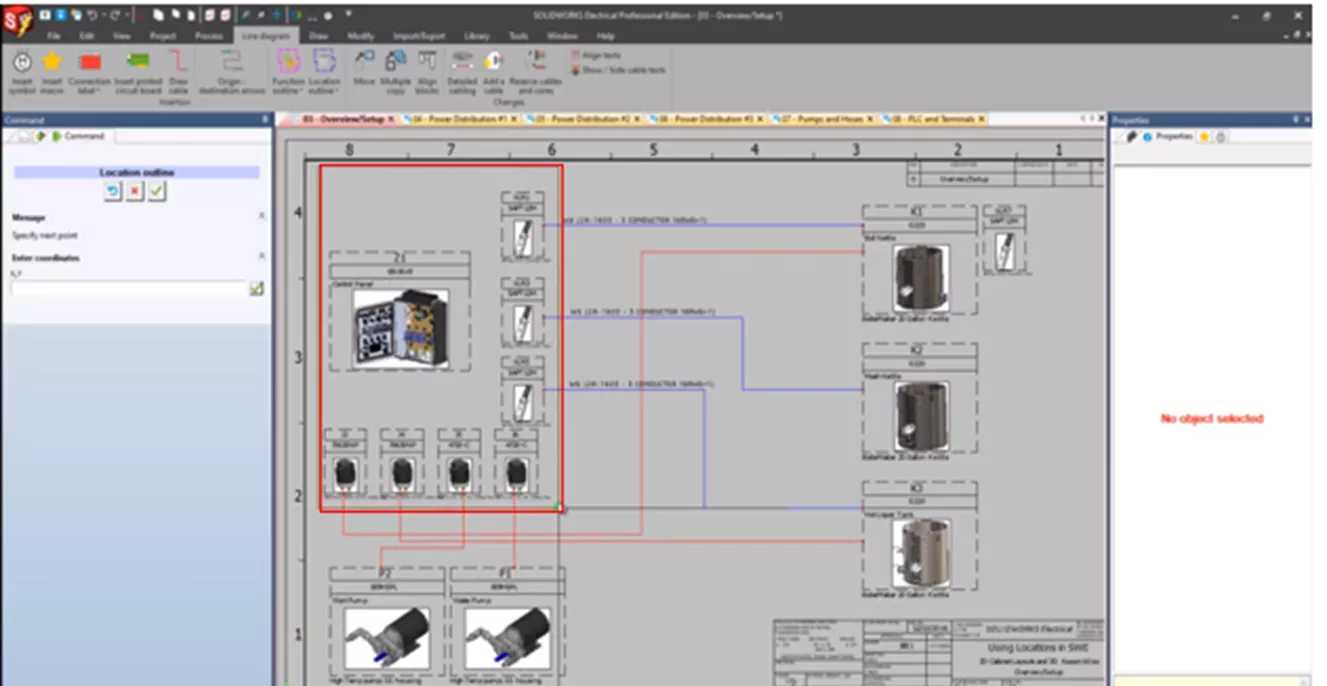
Figure 3: Rectangular Outline
This will bring up the Locations Manager, which lets us assign the location. Here we will set this as the control panel.
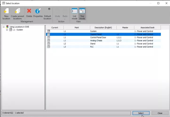
Figure 4: Select Location, Control Panel
When prompted to change the location of the components within the rectangle to this location, we will say yes.
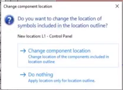
Figure 5: Change Component Location
Now that we have placed one of our locations and assigned it to an already existing location, suppose we want to create a new location.
Our pumps, P1 and P2 at the bottom, are isolated in a separate room called Pump Room. If we go to the Project tab, we'll have access to the Locations Manager, which includes a list of all locations we have within the project. On the left is a collapsable menu, showing sub-locations and the parents of the child locations.
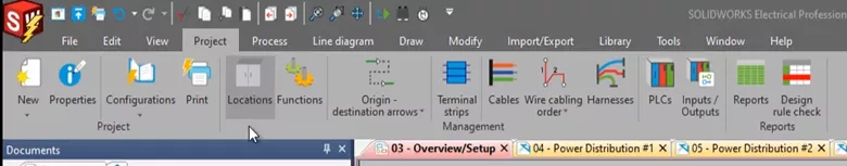
Figure 6: Project Tab, Locations Manager
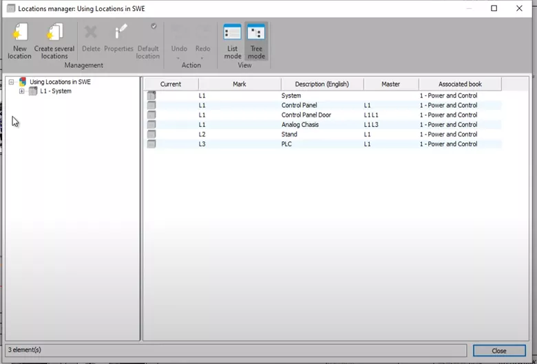
Figure 7: Locations Manager
Select System, a top-level parent location, and create a New Location. This brings up the location properties where it will show you the mark that will be assigned, the Parent Locations, and which Book it is located in.
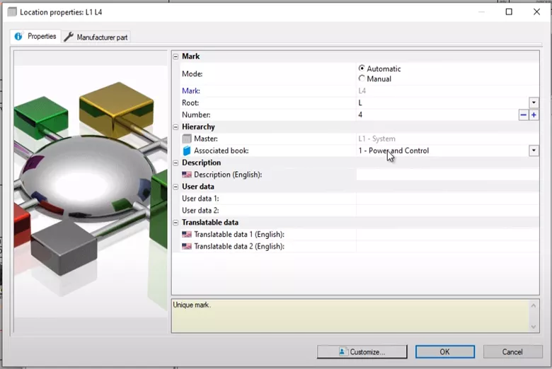
Figure 8: Location Properties
For the description, we will say, Pump Room. Hit OK and it is now placed within the L1 System Location.
We will go back to our Line Diagram tab and repeat the steps for making a location outline. This time for our Pump Room and making sure the rectangle encloses both P1 and P2.
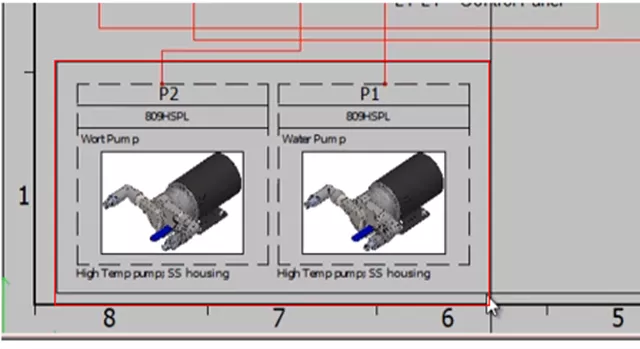
Figure 9: Pump Room Outline
We'll assign the location to be the Pump Room, and change those two components to this new location. L1 is the parent System Location and L4 is the sub Location Pump room.
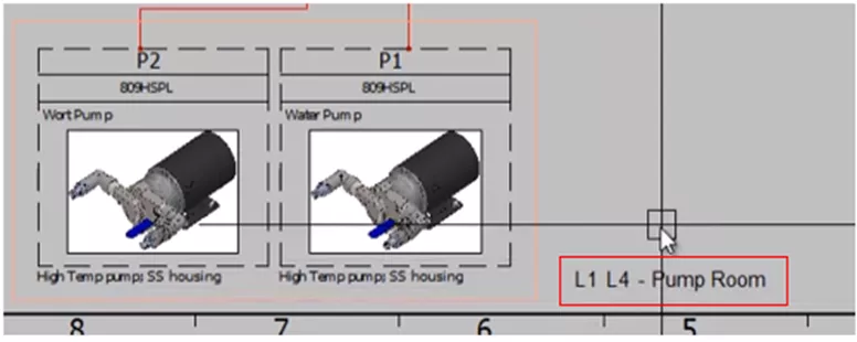
Figure 10: L1 L4 Locations
Component Location Organization
So far we have created a new location, assigned components to this location, and placed them in the Schematic.
An alternative way to use locations is to organize a project with documents. Go to the Document tab and select Components. Here, the Components list is organized by locations and what locations they belong to.
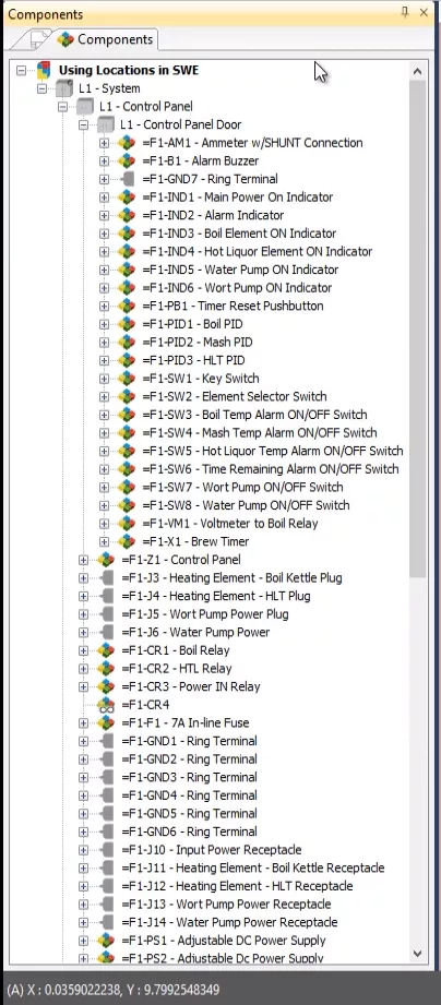
Figure 11: Components Tab
An alternative way to see how our locations can be used or organize a project is by going to the Docuement tab and selecting Components. Here, the Components list is organized by locations and what locations they belong to.
This is helpful if you are looking for a specific component, especially when you have an extensive list of components as we have in this example.
If we expand pump room, we see isolating those two pumps into our new location assigns them in our components tree.
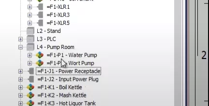
Figure 12: Expand Pump Room Location
We can also go to the specific component itself or the symbol of that component. Right-click and select Symbol Properties.
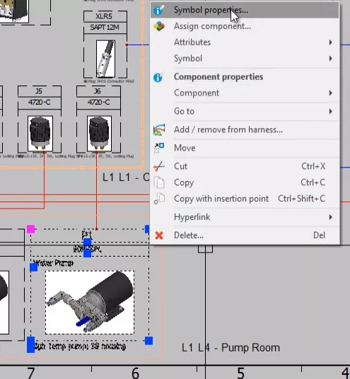
Figure 13: Symbol Properties
This opens the Symbol Properties window where we have the component tree, which is organized by the component location. We also see in the hierarchy the location.
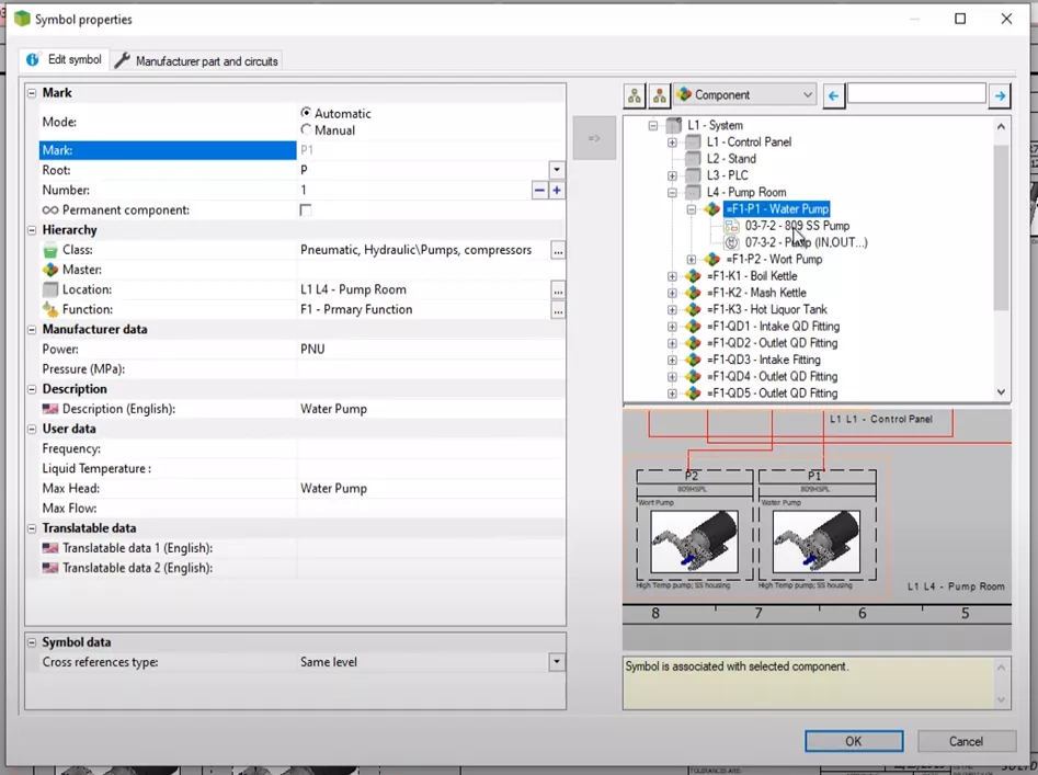
Figure 14: Component Location and Hierarchy
Expanding this brings up the Locations Manager, where we can assign a new location if desired.
2D Cabinet Layouts
At the Process tab, we can create 2D cabinet layouts.
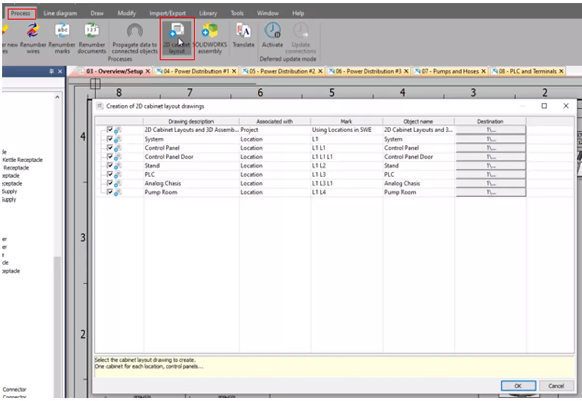
Figure 15: Process Tab, 2D Cabinet Layout
Each 2D cabinet layout will be generated from a location. Each location we created, including the new Pump Room, has the option to generate a new 2D Cabinet Layout Drawing for that specific location. In this example. we will uncheck all of the locations except control panel.
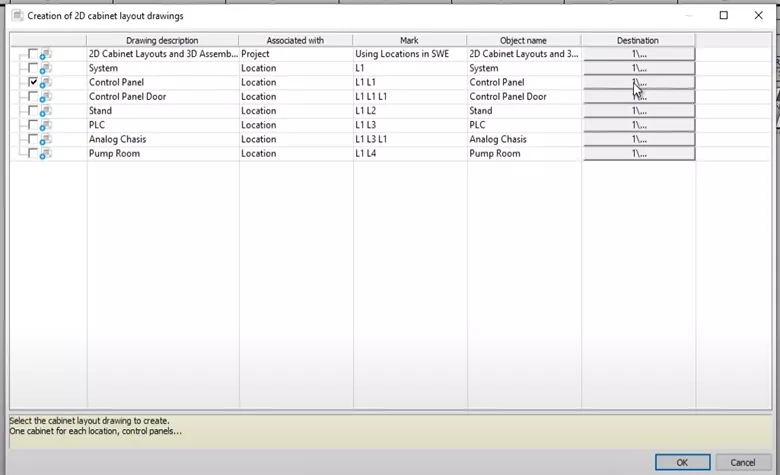
Figure 16: Uncheck All Except Control Panel
At the Destination tab, we can integrate it within our pre-existing 2D Cabinet Layout Folder. Going back to Documents we see the control panel Drawing.
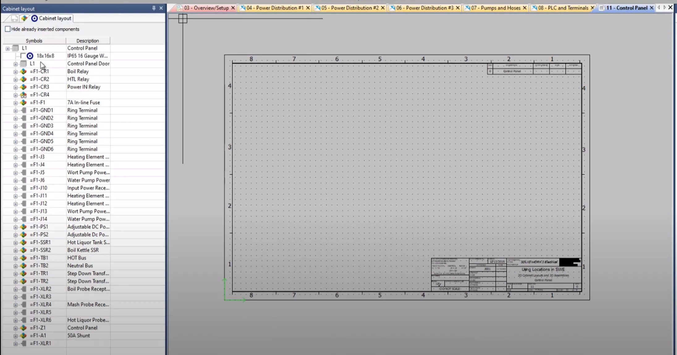
Figure 17: 2D Cabinet Layout Panel Drawing with Component Locations
If we open it, the Cabinet Layout Panel, components, and even the sublocation of the control panel door are listed here. We can begin placing our 2D cabinet footprint.
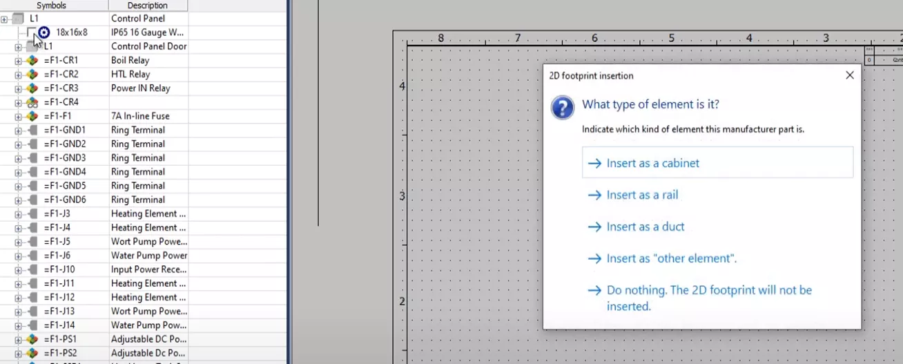
Figure 18: Insert 2D Footprint
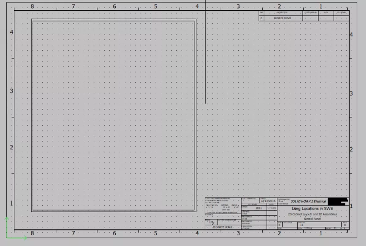
Figure 19: Placing 2D Cabinet Footprints
Another organizational tool is the Project Location function in SOLIDWORKS Assemblies. Here we can generate new 3D assemblies in SOLIDWORKS using SOLIDWORKS Electrical 3D and each one is going to be organized by our locations.
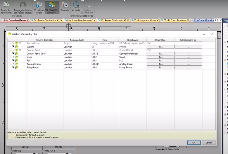
Figure 20: SOLIDWORKS Assemblies Organized by Location
This is especially useful as SOLIDWORKS lets us bring the Electrical intelligence into our 3D SOLIDWORKS assemblies and parts to route wires, and integrate those connections into existing assemblies or new assemblies.
The System Room and Control Panel are greyed out since they have already been generated. We can go into SOLIDWORKS and see it in our ElectricalManager tab here.
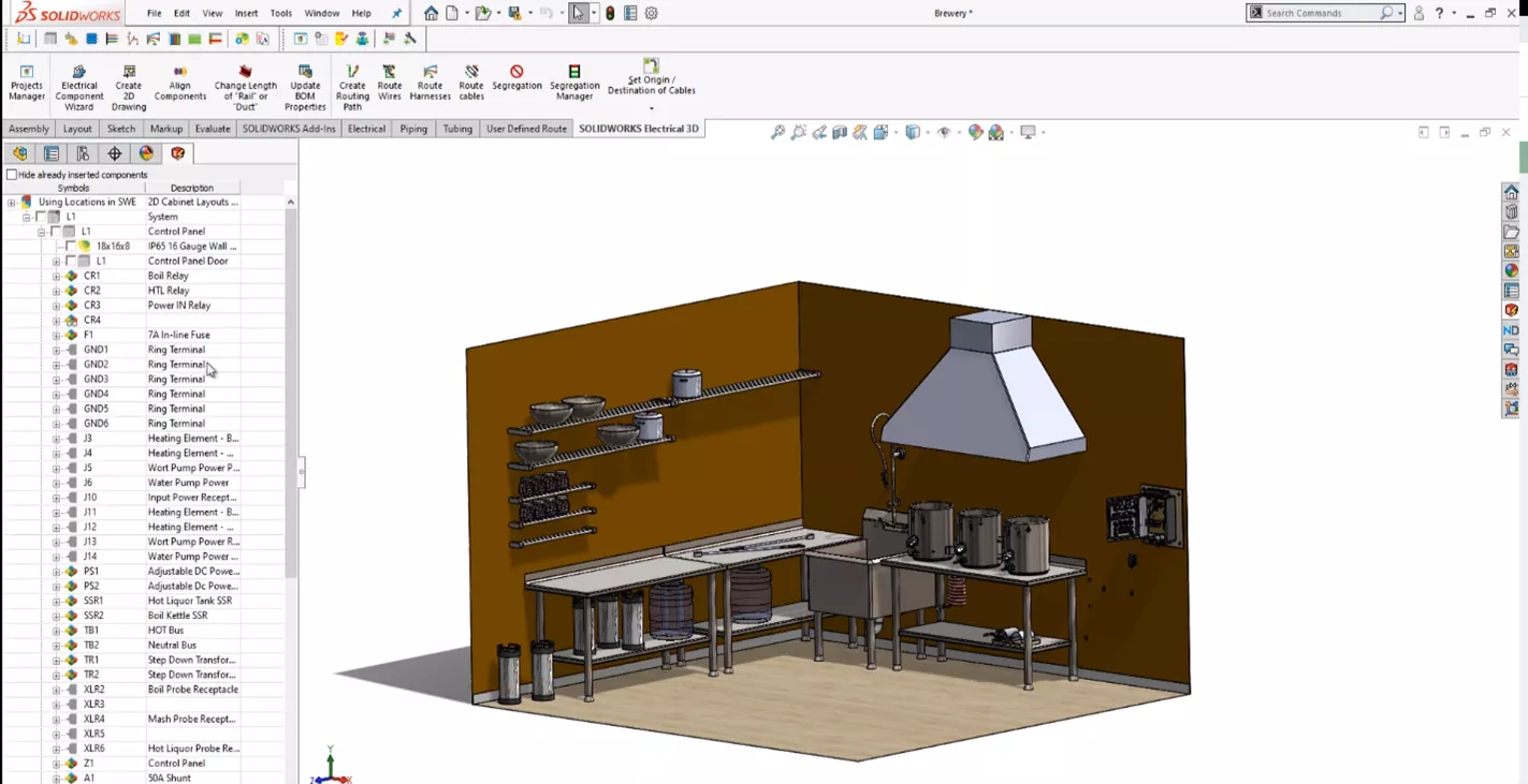
Figure 21: SOLIDWORKS Electrical 3D Tab
Like the components tree organized by location, all of our components are listed here for placement within our new assembly as well as the control panel. All of the components that we have assigned to our control panel Location are listed and if they had not been placed can now insert them into our system.
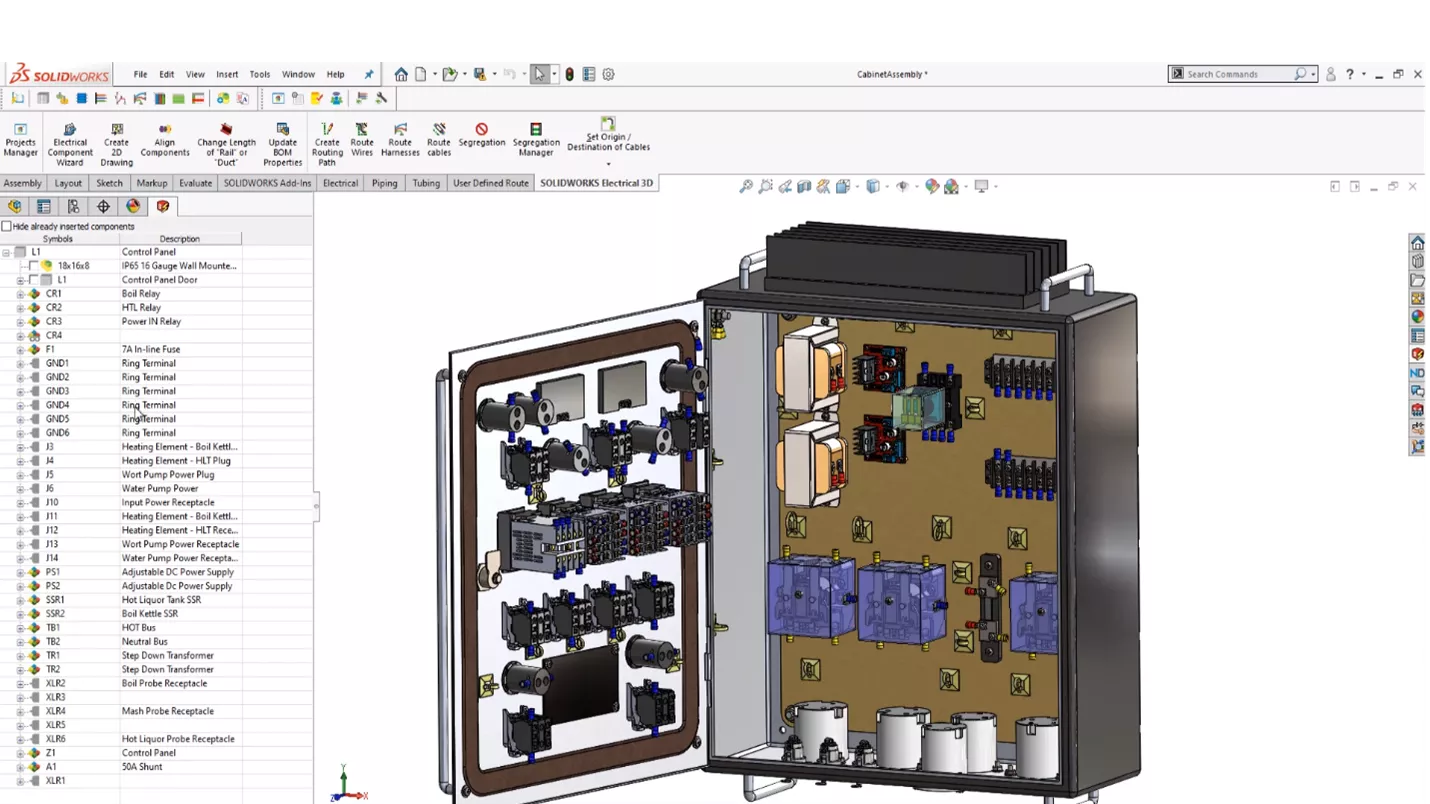
Figure 22: Control Panel in SOLIDWORKS Electrical 3D
We have shown how our locations can be used to organize our project, organize our components, and bring intelligence to our schematics to help us realize the actual reality when it comes to manufacturing and constructing electrical systems.
![]() Want to learn more? Check out this YouTube video demonstrating these tips, tricks, and best practices.
Want to learn more? Check out this YouTube video demonstrating these tips, tricks, and best practices.
More SOLIDWORKS Electrical Tutorials
SOLIDWORKS Electrical vs Routing: Which Product Should I Choose?
SOLIDWORKS Electrical: Wire Mark, Equipotential, and Wire Numbering
Create a SOLIDWORKS Electrical Project Template
SOLIDWORKS Electrical Auto-Archiver Setup
Create New SOLIDWORKS Electrical Symbols By Modifying Existing
![]()
About Nathen Blas
Nathen Blas is a SOLIDWORKS Technical Support Engineer based out of our Headquarters in Salt Lake City, Utah. He earned his Bachelor’s degree in Mechanical Engineering at the University of Utah in 2018 and joined the GoEngineer family that same year.
Get our wide array of technical resources delivered right to your inbox.
Unsubscribe at any time.