SOLIDWORKS Flow Simulation Sliding Mesh Explained
In 2015, a new rotating region option was added to SOLIDWORKS Flow Simulation: Sliding Mesh. The Sliding Mesh assumes an unsteady flow field and is therefore available for transient solutions only.
While this method can be used for various flow configurations, it is especially suitable to provide solutions in cases where the rotor-stator interaction is strong and in cases where the flow exits the rotating component radially.
The beauty of the Sliding Mesh method is that the mesh within the rotating region is updated throughout the calculation to conform to the position of the rotating component. This ensures a more accurate solution. The drawback is that this method is more computationally intensive.
What is the Sliding Mesh Method?
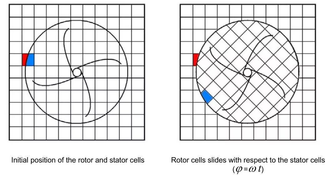
In the Sliding Mesh method, rotor and stator cell zones are connected through a sliding interface. During the calculation, zones linked through the sliding interface remain in contact with each other (i.e., the rotor cells slide relative to stator cells along the interface boundary in discrete steps as shown below). The sliding interface coinciding with the rotating region boundary must be within a fluid volume.
How to Enable the Sliding Mesh Method
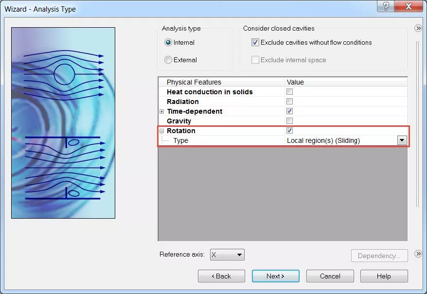
The Sliding Mesh method can be enabled during the creation of a SOLIDWORKS Flow Simulation project when navigating through the new project wizard. The option is available on the Analysis Type tab.
This method can also be enabled after a project is created through the General Settings dialogue window. To enable this method, the Rotation option needs to be enabled and the type needs to be set to Local region(s) (Sliding). Since this method is only available for transient solutions, the Time-dependent option also needs to be enabled.
Transient Solution Manual Time Step Considerations
A manual time step can be defined from within the Calculation Control Options dialogue window. It is recommended to specify a manual time step value of less than 1/50 of the revolution period.
For example, if the rotor speed is 500 RPM, one revolution period would be 0.12 seconds. The manual time step based on this criterion would be: 0.12𝑠/50 = 0.0024 𝑠.
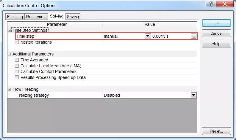
Moreover, the time step value should also be based on the number of rotor blades. This takes into account the absolute time required for one blade to move from its position to the position of the neighboring blade.
For an angular velocity of 500 RPM and a number of rotor blades of 8, the time required for a blade to move from its position to the position of the neighboring blade is ∆𝑡 = 60/500∗8 = 0.015 𝑠.
To properly resolve the fluid behavior, this value can be divided into ten time increments. Therefore, the manual time step can be specified as 0.0015 s.
Local Rotating Region Definition
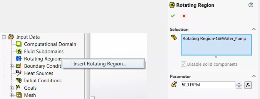
A body of revolution needs to be created to represent the local rotating region. The local rotating region can be defined by right-clicking on the Rotating Regions link under the Input Data section of the SOLIDWORKS Flow Simulation analysis tree.
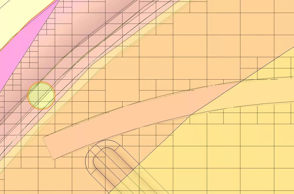
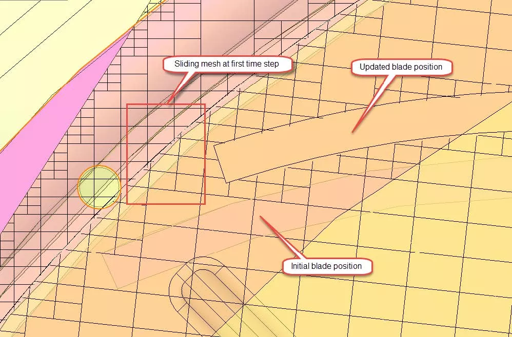
Results
The following screenshots show the initial mesh (physical time of 0 s) and the mesh after the first time step (physical time of 0.0015 s).
Want more SOLIDWORKS Flow Simulation tutorials? Check out some of our top picks below.
More SOLIDWORKS Flow Simulation Tutorials
Understanding the Tesla Valve Using SOLIDWORKS Flow Simulation
Customizing SOLIDWORKS Flow Simulation Feature Tree Categories
Different Pressures in SOLIDWORKS Flow Simulation
Backspin is Important to Your Basketball Free Throw! A SOLIDWORKS Simulation Study
![]()
About GoEngineer
GoEngineer delivers software, technology, and expertise that enable companies to unlock design innovation and deliver better products faster. With more than 40 years of experience and tens of thousands of customers in high tech, medical, machine design, energy and other industries, GoEngineer provides best-in-class design solutions from SOLIDWORKS CAD, Stratasys 3D printing, Creaform & Artec 3D scanning, CAMWorks, PLM, and more
Get our wide array of technical resources delivered right to your inbox.
Unsubscribe at any time.