SOLIDWORKS Simulation Drop Test Tutorial
Drop Tests are a kind of study in SOLIDWORKS Simulation Professional and Premium that simulates dropping a model on the ground. Simulation drop Tests are the only type of study in SOLIDWORKS Professional that utilizes a dynamic solver. Though SOLIDWORKS is performing complex calculations in the background, Drop Tests are easy to set up as a user.
In this article, which is a companion to the video above, we'll run four different Drop Test studies on a simple camera assembly consisting primarily of a two-sided case and a lens. An angled plane named horizontal has been added to the assembly to represent the ground.
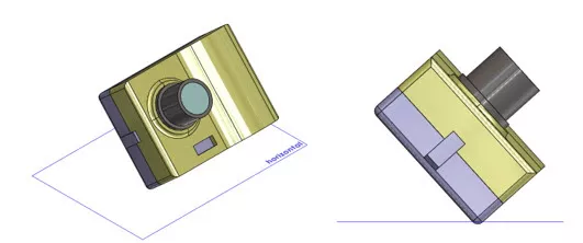
FIG. 1: Isometric (left) and front (right) views of camera assembly
Study 1: Linear material model, bonded global contact, perfectly rigid ground plane
We start setting up a Drop Test the way we would most SOLIDWORKS Simulation studies, by applying materials and defining contact sets.
To apply a material to a component, right-click it under Parts in your study tree and select Apply/Edit Materials.
Select the material you want in the Material dialog that pops up then click the Apply button.
By default, a global bonded interaction will be created under Component Interactions in the Connections section of the study tree. For this study, we will leave this as-is; we want to assume that, wherever the camera components are touching, they are fused together and will behave as if they are one piece.
All the Drop Test settings are contained in Drop Test Setup, which you access by double-clicking Setup or right-clicking it and selecting Define/Edit.
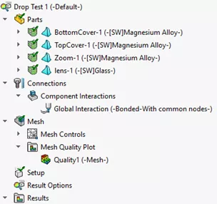
FIG. 2: Drop Test Study tree
We can define the parameters of the camera's fall either by setting the height from which it's dropped (Drop height) or its velocity when it hits the ground (Velocity at impact). In these cases, we're using height.
We'll be dropping the camera from 2 meters, measured from its centroid, above the ground. We're using normal gravity. If we wanted to simulate the camera being thrown to the ground as opposed to just falling, then we can increase the gravity's magnitude. To determine the direction of gravity, we'll select the horizontal plane we created.
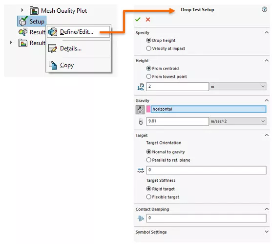
FIG. 3: Drop Test Setup tree item (left), FIG. 4: Drop Test Setup PropertyManager (right)
Next, we'll fill in information about the Target or impact plane. In all the cases we're examining in this article, the impact plane is normal to gravity and there is no friction between the model and the ground. In this first case, we're assuming the ground is perfectly rigid.
Because we aren't modeling air, the model is not spinning. It will strike the ground in the orientation in which it's falling.
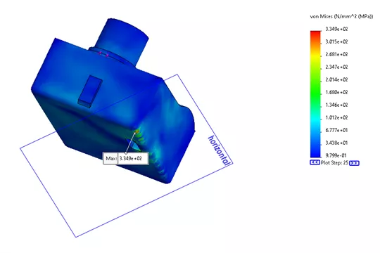
FIG. 5: Results of first Drop Test
Study #2. Linear material model, bonded global contact, Flexible Layer on ground plane
In our next example, we will be changing our Drop Test Setup to add flexibility to the floor.
For example, if the camera is dropped on a wooden floor in real life, we'd expect a certain amount of flex in the wood when the camera hits it. Everything else, the material, the mesh, and the contact conditions, will remain the same.
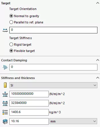
FIG. 6: Drop Test Setup PropertyManager with Flexible target
In the Target section of the Drop Test Setup PropertyManager, select the radio button for Flexible target under Target Stiffness.
This causes a new section titled Stiffness and thickness to appear.
We can now define the floor's stiffness in two directions, normal and tangential, and its density and thickness.
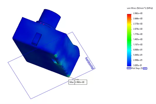
FIG. 7: Results of second Drop Test
The maximum stress is less than in our original study.
Study #3. NonLinear material model, bonded global contact, Perfectly Rigid ground plane
In the next study, we're returning to a perfectly rigid impact plane, leaving the bonded global contact, and changing the material to a nonlinear one.
Originally, the camera's body was Magnesium Alloy from the SOLIDWORKS out-of-the-box materials library. It uses a linear material model.
To create a custom, nonlinear version of this material, we copy and paste the SOLIDWORKS material into a custom folder in our materials dialog. For more details, read the article titled Create Custom Materials in SOLIDWORKS.
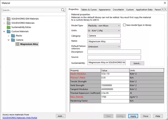
FIG. 8: Custom material settings
This copied custom material is fully editable, allowing us to change the material model to Plasticity - von Mises and define a Tangent Modulus.
Our custom Magnesium Alloy is bilinear. A bilinear material model is more accurate here because it will enter a plastic zone and the stiffness will change.
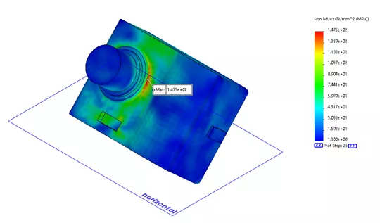
FIG. 9: Results of third Drop Test
Again, our maximum stress is less than in our original study.
Study #4. Linear material model, Local Contact Interaction, perfectly rigid ground plane
In this example, we're using a linear material model again and a perfectly rigid ground plane. However, we'll also be suppressing the automatically created global bonded interaction and adding a local contact interaction between the faces where the two halves of the case touch. This prevents these two faces from passing through each other, but otherwise does not restrict their movement or fuse them together.
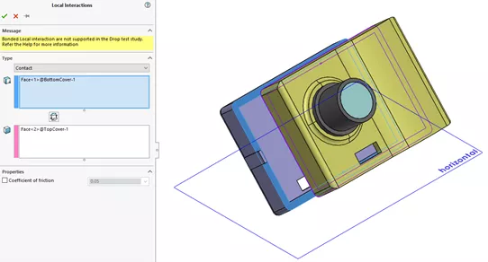
FIG. 10: Local Contact Interaction
To understand the results of this study better, we can right-click the Stress1 (-vonMises-) result plot while it is active and select the option for Animate.
This will display an animation of the camera's fall and the resulting stresses.
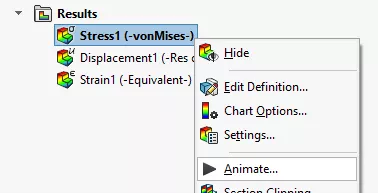
FIG. 11: Animate option in stress result right click menu
The frames in this animation are actual calculated time steps from the explicit dynamic solver. The big difference between this study and the others is that the location of the maximum stress has shifted from the bottom edge of the camera where it strikes the floor to the fasteners.
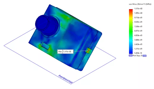
FIG. 12: Results of fourth Drop Test
There are many free SOLIDWORKS Simulation tutorials available within the software. However, if you'd like to learn more about the various studies and analyses that can be performed in SOLIDWORKS Simulation, check out some of the articles below.
Related Articles
SOLIDWORKS Motion Study Analysis and Setup Tutorial
Introduction to Validation Equations in SOLIDWORKS Simulation
Introduction to Structural Analysis Using SOLIDWORKS Simulation Tools
SOLIDWORKS Simulation Tips: No Penetration Contact Set Setup
7 Steps to Perform a Fatigue Analysis in SOLIDWORKS Simulation

About Lauren McGarry
Lauren McGarry is a Certified SOLIDWORKS Expert based out of San Diego, California. She earned her Bachelor of Science degree from Case Western Reserve University and has been with GoEngineer as a Technical Support Engineer since 2016.
Get our wide array of technical resources delivered right to your inbox.
Unsubscribe at any time.