SOLIDWORKS Tutorial: Using Split Lines with Variable Size Fillets
In SOLIDWORKS, Variable Size Fillets have different radii at different points along the selected edges. The user can specify the radius at the edges' endpoints and at control points along the edges' length.
If you've used this feature before, you may have noticed that, while it's possible to set the radius to zero at the end-points of an edge, it isn't possible to specify a zero radius at any of the intermediate control points. If you try, when you click away or press enter to confirm your selection, the value reverts to what it was before you made the change.
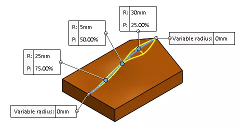
Figure 1: Variable Size Fillet
As a solution, we can use the Split Line feature to break the edge we're filleting where we want the radius to be zero, creating an endpoint there.
![]() This article is a companion to this Quick Tip video.
This article is a companion to this Quick Tip video.
Creating a Projection Type Split Line
SOLIDWORKS Split Lines break up faces and create model edges where they would not normally exist. They do not change the geometry of the faces being split. In this case, we can use them to divide the single edge we want to fillet into multiple edges with endpoints where we want to set the radius to be zero.
In this example, we are using a Projection type Split Line, which projects a 2D sketch onto selected faces.
We start by creating a 2D sketch where we want to split the edge.
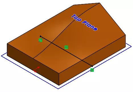
Figure 2: 2D Sketch for use in Split Line
The Split Line command is available under the Curves dropdown in the Features tab of your CommandManager or in Insert > Curves > Split Line.
In the Split Line PropertyManager, select Projection as the Type of Split, then select your sketch and the faces you want to split - the ones adjacent to the edge we are filleting.
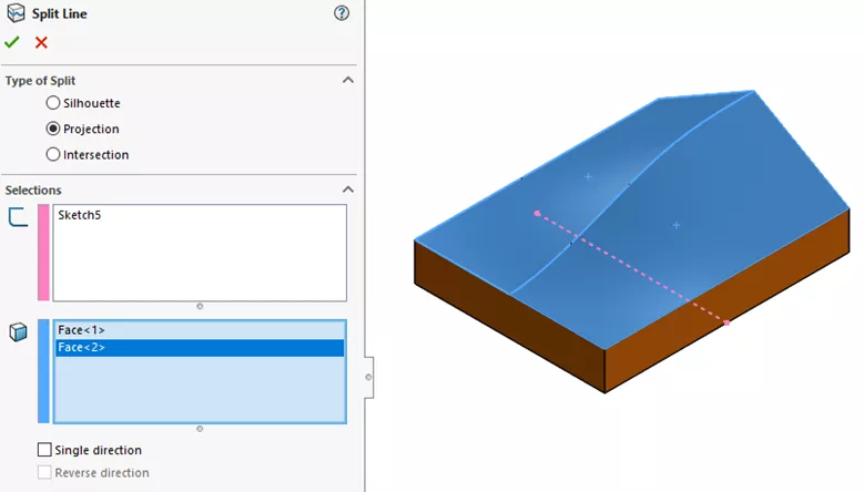
Figure 3: Split Line PropertyManager
The result is the two faces are both divided in two, creating four faces total, all of which can be selected separately.
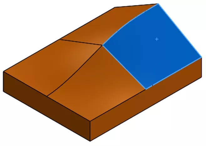
Figure 4: Part following Split Line feature with one face selected
The two halves of the edge can now also be selected separately in the Split Line PropertyManager and elsewhere. Now that there is an endpoint the center of the edge, we can set the radius at that location to zero.
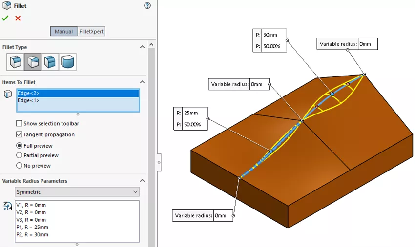
Figure 5: Variable Size Fillet PropertyManager with edges created by Split Line selected
Want to Become An Expert?
Take the official SOLIDWORKS Advanced Part Modeling self-paced training course to learn more about working with these features, commands, and design tools.

I hope you found this tutorial helpful. Check out more SOLIDWORKS tips and tricks below.
More SOLIDWORKS tutorials
SOLIDWORKS Variable Pattern Tool Explained
SOLIDWORKS Mold Tools: Split Line & Parting Line Explained
SOLIDWORKS: Splitting a Body into Multiple Parts
Ultimate Guide to SOLIDWORKS Splines

About Lauren McGarry
Lauren McGarry is a Certified SOLIDWORKS Expert based out of San Diego, California. She earned her Bachelor of Science degree from Case Western Reserve University and has been with GoEngineer as a Technical Support Engineer since 2016.
Get our wide array of technical resources delivered right to your inbox.
Unsubscribe at any time.