Create Custom SOLIDWORKS Electrical Routing Component
Routing is an application included in SOLIDWORKS Premium that helps automate different types of routes, including electrical. Included in SOLIDWORKS is an extensive library of intelligent components you can drag and drop into your route. This default library is called the Design Library.
If you have the SOLIDWORKS Routing Add-in, you can add intelligent custom components to the library. You can also create custom components that have routing information which automatically start a route just like the ones already included in the Design Library.
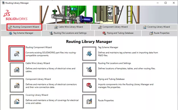
The Routing Component Wizard, included in the Routing Library Manager, can be used to add intelligence to components and provides all the steps needed to add the mandatory and optional routing features.
Adding custom SOLIDWORKS electrical routing components to the Design Library
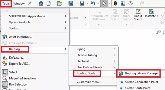
To get started, open up the connector part in its own window that already has geometry in it, then go to the Routing Component Wizard.
Go to Tools > Routing > Routing Tools > Routing Library Manager.
Then select the Routing Component Wizard tab.
In this example, we will set up an electrical connector.
Make sure to open up the connector model you want to work on before you select Routing Library Manager.
Select the type of Route (in this case Electrical), and then the type of Component (for this example it is a Connector).
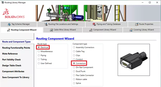
You will see a generic preview of a connector, but it is not associated to the connector you are working with.
Select Next in the lower right corner to navigate through to the next step.
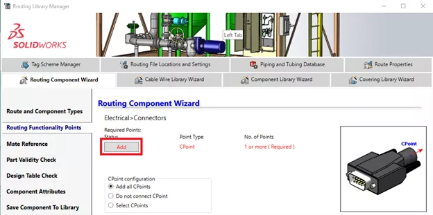
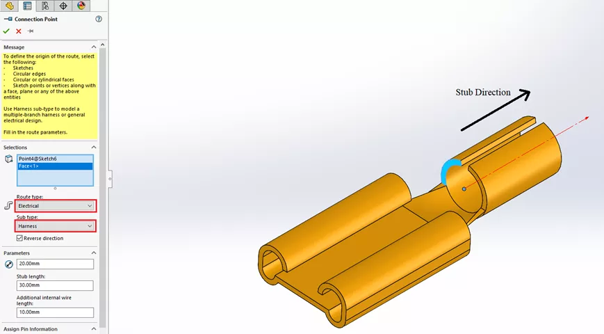
How to add a connection point
All connectors need at least on one Connection Point or CPoint. Select the Add button to create the mandatory CPoint.
The Wizard will minimize and will then switch back to the SOLIDWORKS graphics area. This will allow for you to select a Plane/Face and a sketch point to locate the connection point.
Set the direction to go outside of the connector (which is the conduit direction).
Set the Route type and Sub type. The stub length is how far the straight portion of the wire goes out the back of the connector. Set the Nominal diameter of the route and the additional internal wire length. The additonal internal wire length can be set to zero.
After you complete each step, the Routing Component Wizard reopens to guide you through the next step.
Optionally, after creating the first mandatory Cpoint, you can add more.
You will see a Red, Green, and Blue Legend color coding what has been added, what is still needed, and what is optional.
Green steps are required and have been satisfied. Red still need to be set up. Blue are optional.
Select Next.
Mate References
This step is optional, but when it comes to connectors you want at least one mate reference (up to to three depending on the geometry).
Mate References automatically applies mates when dragging components into the assembly. You can add the Mate References before you use the Wizard (it will recognize them) or you can put them in using the Routing Component Wizard.
In this example, we will use three Coincident references with the anti-align alignment option. Rule of thumb, if the end of the connector has circular geometry, select one of the circular edges and select Default for type and Any for the alignment type. For this particular connector, select larger faces first.
Select Next and complete the rest of the steps.
The picture below shows the options and the three different colored faces selected.
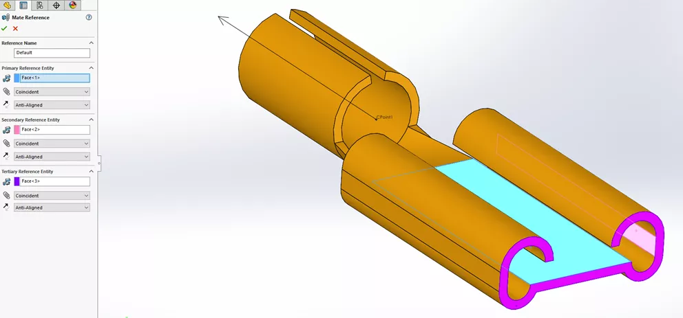
You can select up to three Mate References. Mate references should be tested and the order of the face selections can change how well they work in the assembly.
Select Next.
Part Validity Check will verify if anything is missing. (Part modeling is complete)
Select Next.
A Design Table can be created, but it is not mandatory if you are only using one configuration of a part.
Optional custom properties can be added here. Once complete, select Next.
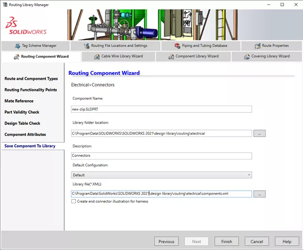
Save Components To Library
Make sure the part file is saved properly in the library.
Name the connector part.
Store in the same location as the Design Library. You might be using a network folder location so make sure you place it with the rest of the routing compnents.
The default Design Library location is a hidden folder: (C:\ProgramData\SOLIDWORKS\SOLIDWORKS 20XX\design library).
The picture below shows the folder location and library file location.
Select Finish.
Once you see the Save is successful message, you can close the Wizard and the Routing Library Manager.
Refresh the Design Library Folder you placed the connector in to see it and to test out your new routing part.
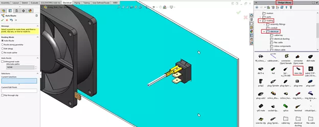
Now, when you drag in the newly customized connector from the Design Library located in the Task Pane into an existing assembly, it will snap into place using the mate referennces and start a new electrical route.
The image below shows the connector first being placed showing the new route stub out of the back of the custom connector and the Auto Route dialog box on the left side.
The Routing Component Wizard setup steps outlined above work in the same way for piping and tubing routing components.
Troubleshooting
If the new connector does not automatically start the new route (no stub creation out the back of the connector):
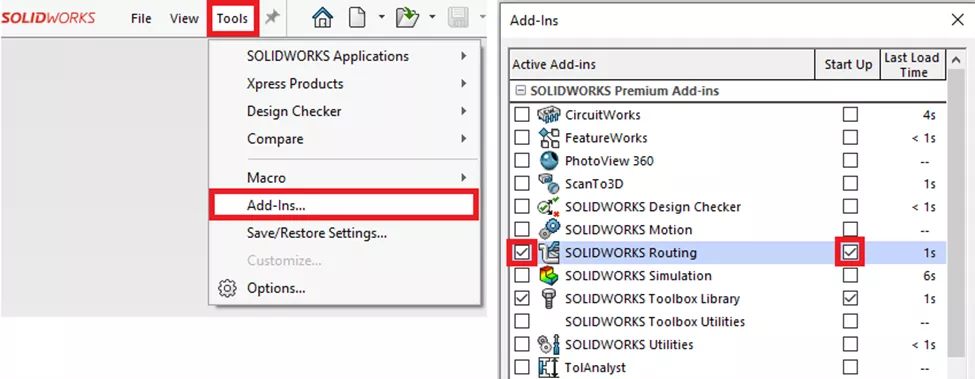
- Check to make sure the Routing Add-in is turned on. Navigate to Tools > Add-Ins > enable the check box for SOLIDWORKS Routing in the left column for it to open in the current session of SOLIDWORKS.
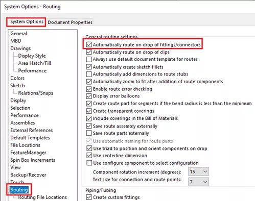
- There is also a setting to automatically start a new route on drag in of new connector or new clip. Check to make sure that is turned on shown below.
Adding intelligence to your custom route parts will help automate the placement of electrical connectors in your assemblies and speed up route creation.
Want to become an expert?
Take the official SOLIDWORKS Routing: Piping and tubing course from GoEngineer.
Learn More about SOLIDWORKS Routing
![]() SOLIDWORKS - Custom Routing Electrical Components
SOLIDWORKS - Custom Routing Electrical Components
Updating the SOLIDWORKS Routing Database
SOLIDWORKS Routing 101: Pipe Design
SOLIDWORKS Content: Download Additional Routing Libraries
What's New SOLIDWORKS 2022: Routing, Structure Systems, Parts & Features

About Maurice Cherian
Maurice Cherian is Technical Support Engineer at GoEngineer. He was introduced to CAD while working for the Navy. Maurice has over seventeen years of Software Training and overall CAD experience. He has been using SOLIDWORKS since 2008 and is a certified expert and instructor. He provides SOLIDWORKS training and Tech Support. Maurice is active in the SOLIDWORKS User Group Community in San Diego, presenting and hosting multiple times over the last eleven years.
Get our wide array of technical resources delivered right to your inbox.
Unsubscribe at any time.