SOLIDWORKS Routing 101: Pipe Design
In this blog, we will explore the basics of SOLIDWORKS Routing for Pipe Design. In this tutorial, we will cover the following topics:
- How to turn on the SOLIDWORKS Routing add-in
- How to access the Routing Library
- How to start a Pipe Route using Flanges
- Overview of Routing PropertyManager
- How to create a SOLIDWORKS Drawing of the Pipe Route.
- How to edit the Route and manipulate 3D Sketches
- How to add Flanges, Straight T, and Valves to complete the design
- Separate the design for shipping by placing Flanges where spools will be taken apart, and use the Spool Feature to group the components accordingly.
To learn the basics of Pipe Routes in SOLIDWORKS and for an overview of routing and pipe design check out the article SOLIDWORKS Pipe Route Overview.
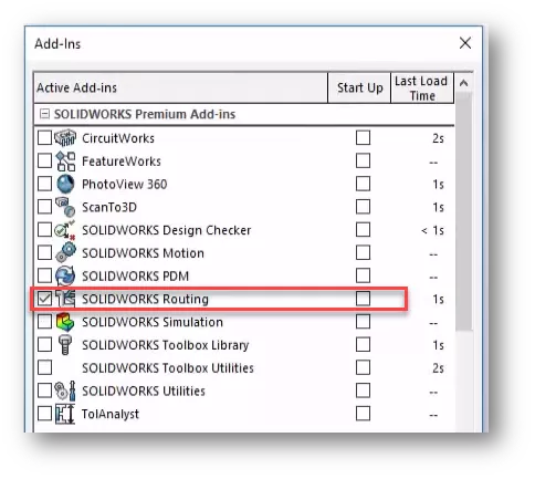
How To Turn On The SOLIDWORKS Routing Add-in
Go to Tools > Add-ins, check the box for SOLIDWORKS Routing on the Active side. Checking the box on Start Up side will cause the Routing add-in to load when SOLIDWORKS is launched.
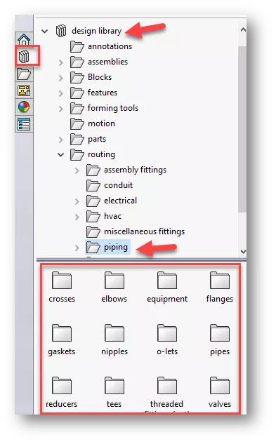
How To Access Routing Design Library
The SOLIDWORKS Design Library is located in the SOLIDWORKS Task Pane. Expand the Design Library folder to see the Routing subfolder. Located below the Routing folder, the Piping folder includes all components needed to create the Piping Route.
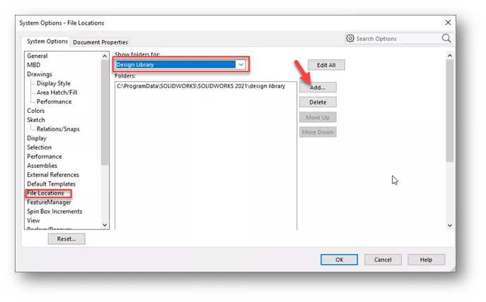
Note: If you do not see the Design Library, go to Tools > Options > System Options > File locations > Routing, and click the Add button. The default folder for the Design Library is C\ProgramData\SOLIDWORKS\SOLIDWORKS 20XX\Design Library.
Starting A Piping Route
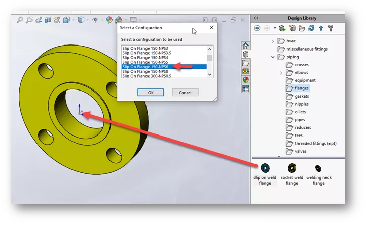
- For this tutorial, we will begin by opening a new assembly in SOLIDWORKS
- Next, browse to the Flanges folder under the Piping folder in the Design Library
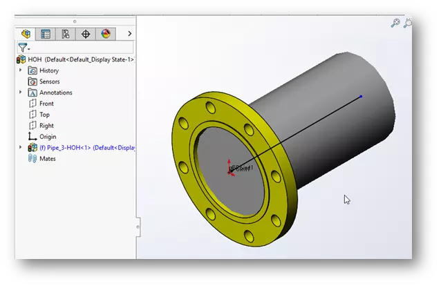
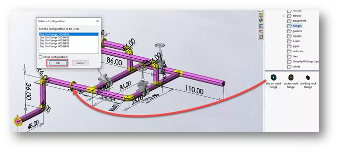
- Drag the slip on weld flange from the Design Library to the Origin of the assembly
- Select the configuration Slip On Flange 150-NPS6 and click OK
- After clicking OK, the Route Property Manager is displayed in the Design Manager Feature Tree.
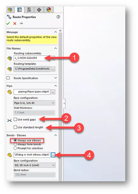
Route PropertyManager Overview
- File Names > Routing Subassembly shows the nomenclature for the Routing Subassembly that will be created.
- Under the Pipe Category, you can select Use Weld Gaps if you would like to add a gap between components.
- The Use Standard Length option will divide the pipe into standard purchased lengths. So, if you buy pipe in 20ft lengths it will divide the pipe into 20ft sections.
- Under Bends – Elbows, set the option to Always use elbows. For this tutorial, we are using a 90deg short radius elbow. You can click the browse button to find the component. Click OK in the Route PropertyManager.
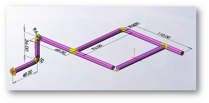
Creating The Pipe Route
Once you click OK in the Piping PropertyManager, you will see a new Routing Subassembly in your Feature Tree. You will also notice that a 3D Sketch has been placed at the origin of the flange. The 3D Sketch is the path the pipe will be swept along.
- On the Piping Toolbar or Sketch Toolbar choose the Line Tool. Start the next line at the endpoint of the 3D sketch. Drag the Line upwards and click the second point.
- If the line is not going in the right direction, you can toggle the direction by hitting the Tab key. This changes the orientation of the sketch from YZ, to ZX, to XY.
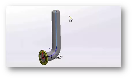
- After you place the line, an elbow is placed to join the pipe. The radius is determined by the elbow chosen in the Routing PropertyManager.
- Continue adding lines. Dimension each segment by clicking Smart Dimension and selecting a line segment. The dimension goes to virtual sharp of radius if there is a change in direction of the pipe.
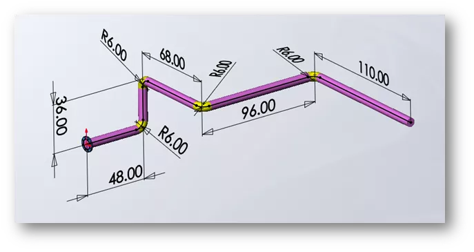
- You can delete a radius to remove the elbow.
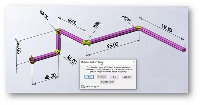
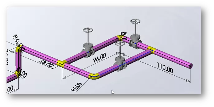
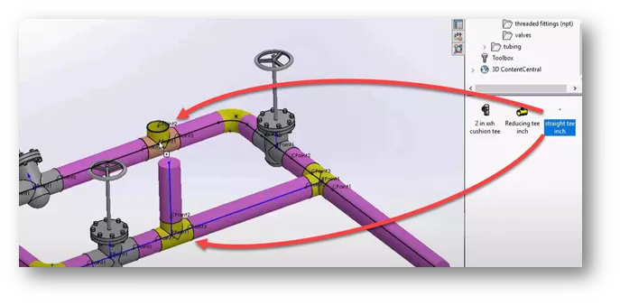
- Click the Line Tool again and add the lines shown below, then we will add a straight tee to the junction.
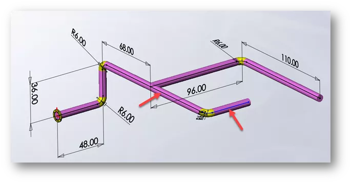
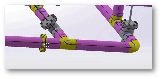
- Drag a straight tee from the Piping Library, Tees folder to the junction and select OK for the default configuration. Notice the tee snaps to the correct orientation based on the 3D Sketch.
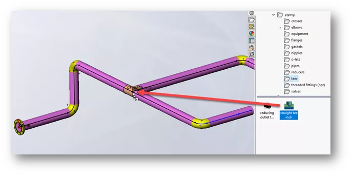
- Drag another straight tee from the Piping Library, Tees folder to this area of the Pipe Route. If the Tee is not orientated correctly, hit the Tab key on your keyboard to flip orientation. Click to place tee, then click OK for the configuration. Notice a 3D Sketch line now coming from the tee.
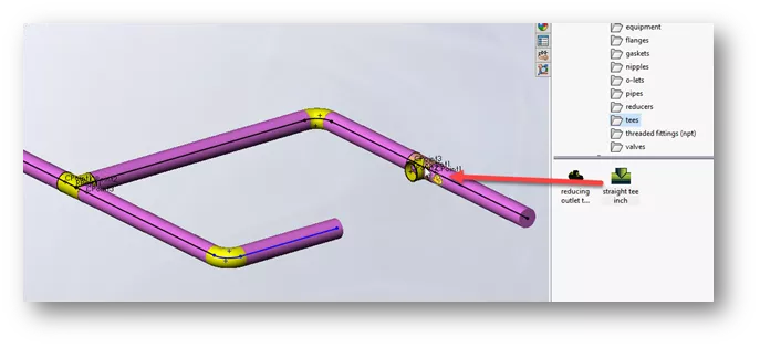
- Delete the sketch line coming from the elbow, then drag the line endpoint (coming from the tee), to the endpoint of the line where we deleted the radius. Then close the sketch in the Confirmation Corner.

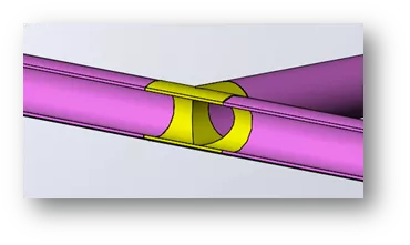
Note: Section view shows how components are created when the Pipe Route is finished.
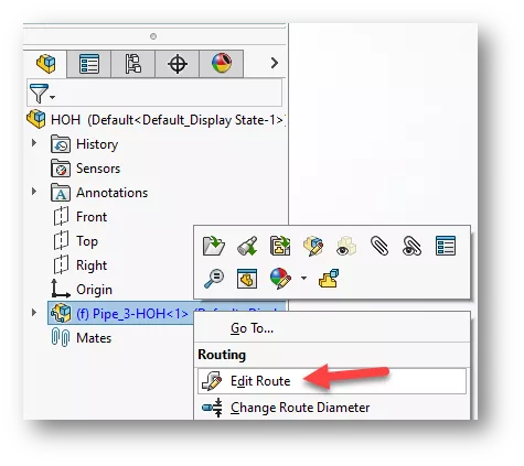
How To Edit the Route
- To edit the route, right-click on the Routing Subassembly and choose Edit Route, or choose Edit Route on the Piping Toolbar.
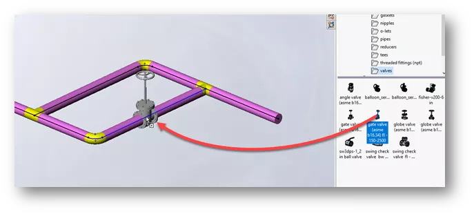
Edit Pipe Route and Adding Valves
- Drag a gate valve from the Piping, Valves folder and drop it on a sketch line. Again, the Tab key controls the orientation of the valve.
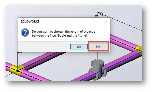
- Click No to shorten the length of the pipe between the Pipe Nipple and fitting.
- Drag over two more gate valves. Click No to shorten the length for each.
- Right-click on a gate valve face and choose Move Fitting with Triad.
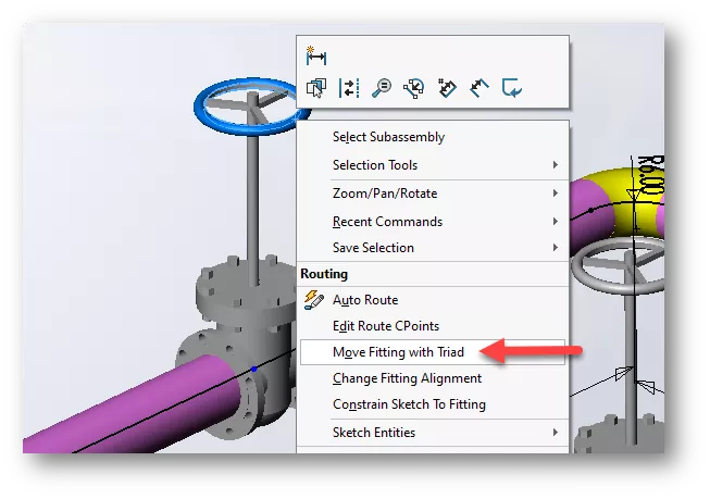
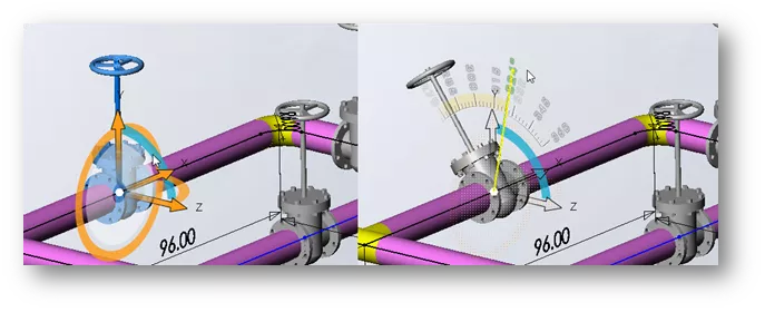
- We can rotate the valve at any desired angle using the Triad Wheels.
- Drag over two more straight tees from the Piping, Tees folder.
- Add a line in the ZX direction (Tab key for orientation) to both tee sketches.
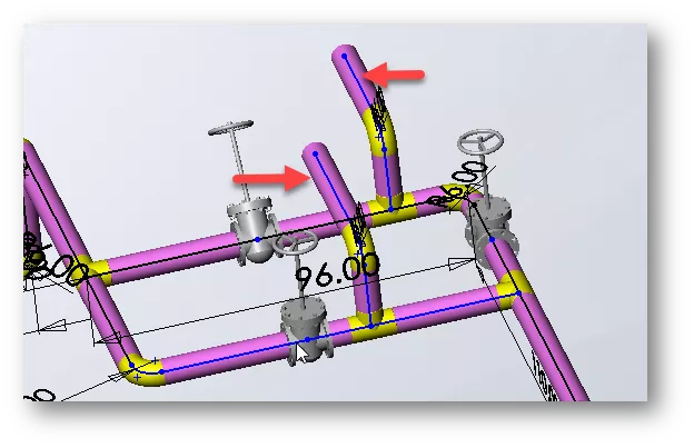
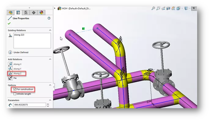
- We can add a Construction Line between the two endpoints, then apply an Along Z relationship to line them up. Finish adding dimensions to the sketches as desired.
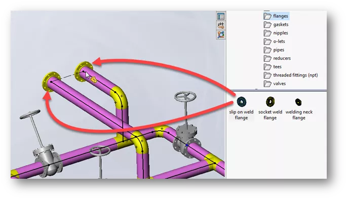
- To finish up the design, drag over two slip on weld flanges to the ends of each sketch. Choose Ok to the default configuration.
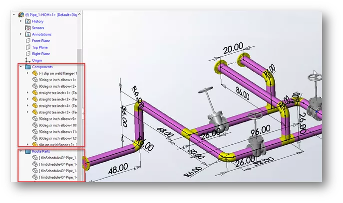
- Notice the two folders in the Feature Tree. The Components folder contains all the flanges, valves, tees, etc. The Route Parts folder contains all piping components.
Using The Spool Feature to Separate Design
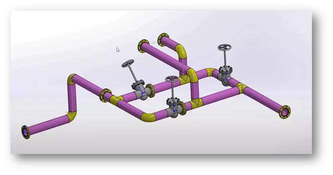
After the Pipe Route is complete, we can use the Spool Feature to separate the design into smaller, shippable spools.
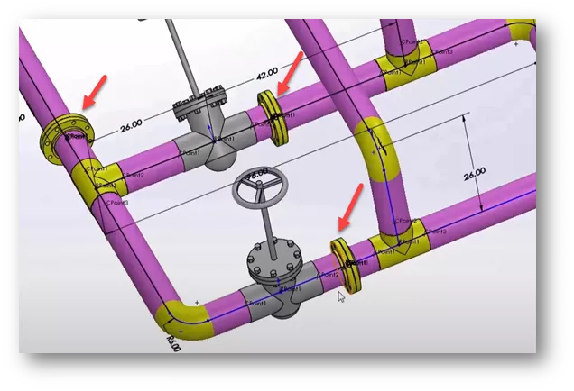
For this exercise, we will split the design up into three smaller segments. First, we need to drag over some slip on flanges where we want to break up the design.
- Drag over another slip on flange and line it up with the previous flange. Watch for the Cursor Feedback that indicates the flanges will be connected, then release the mouse button.
- Add flanges in the same manner to two other locations on the spool.
- We can right-click on one of the pipes between the valve and the segment and choose Remove Pipe.
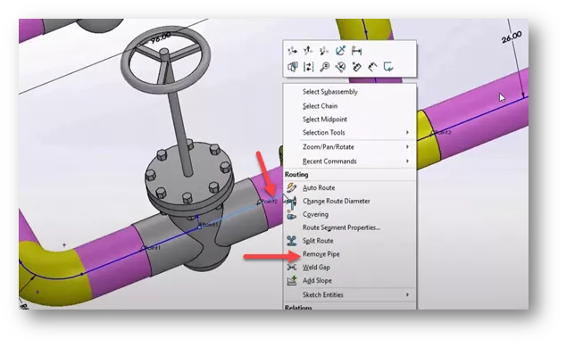
- The pipe is removed and the flanges move next to the valve. Do this for the other pipe between the flange and valve as well.
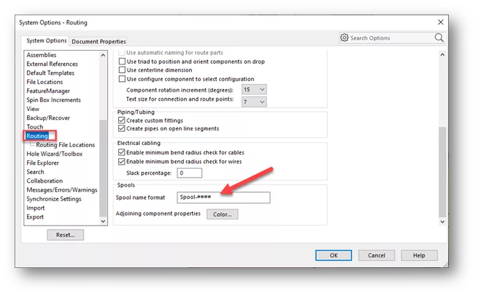
- Before we define the segments with the Spool Feature, we can set up the naming convention for the spools. Go to Tools > Options > System Options > Routing > Spool name format.
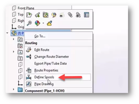
- To define the spool segments, right-click on the Routing Subassembly, and choose Define Spools.
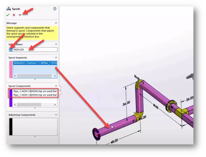
- In the Spools PropertyManager, you can change the name of the Spool and define a color. Click the Push Pin to keep the dialog up after clicking OK.
- For Spool Segments, click one of the line segments at the beginning of the route. In the Spool Components section, it will add the components for the segment.
- Click OK.
- Change the color and name of the second Spool. For Spool Segments, we have chosen all sketch lines in this segment, because of the junction where the pipe splits at the tee.
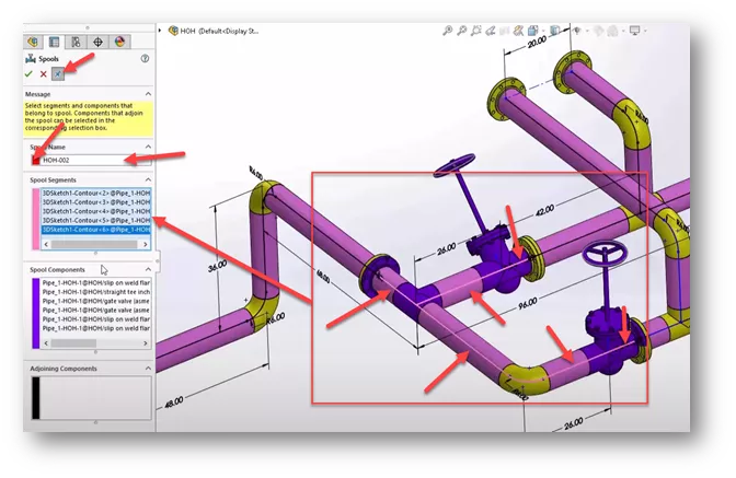
- Change the color and name of the third Spool. Select all the line segments highlighted in magenta below, then click OK and unpin the PropertyManager.

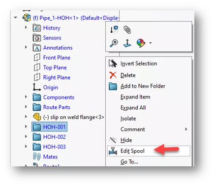
- Each Spool is located in a folder under the Routing Subassembly. If you need to edit a segment, right-click on the folder and choose Edit Spool.
Creating A Spool Drawing
We can use the Pipe Drawing command to quickly create a drawing with multiple sheets, drawing views, BOM’s, and balloons.
- In the main assembly, preselect the Routing Subassembly, and choose Pipe Drawing from the Piping Toolbar.
- In the SPOOL Drawing PropertyManager, select the three spools under Spool Selection.
- Choose a Drawing template, Sheet format, and Piping BOM template.
- Select Include auto balloons.
- Choose View on separate sheet. This will place each spool on a separate sheet.
- You can choose to Show route sketch or unselect to hide the sketches.
- Click OK.
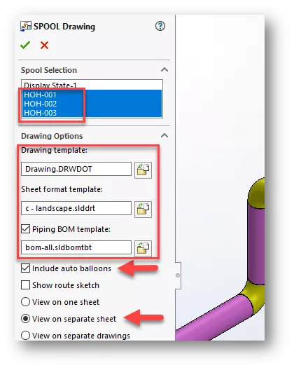
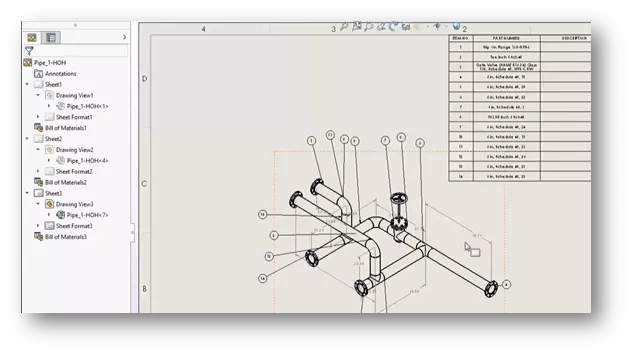
- A drawing is generated with a sheet for each spool, along with balloons and BOM’s.
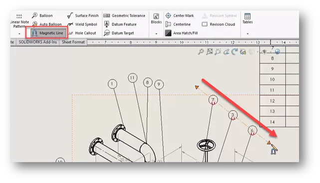
Cleaning Up the Drawing
For the remainder of this tutorial, we will look at a couple of tools to quickly clean up this drawing.
- On the Annotations Toolbar, choose Magnetic Line. Drag the Magnetic Line through a set of balloons. The balloons snap to the line. The Magnetic Line can be dragged around and the balloons will stay attached to the line.
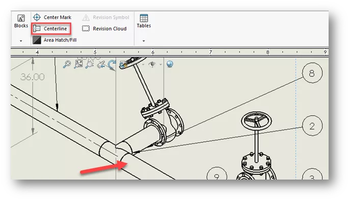
- On the Annotations Toolbar, choose Centerline. Click on each pipe to add Centerlines.
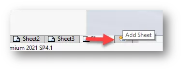
- Let's add a sheet to show a view of the whole spool assembly. Click Add Sheet button next to Sheet3.
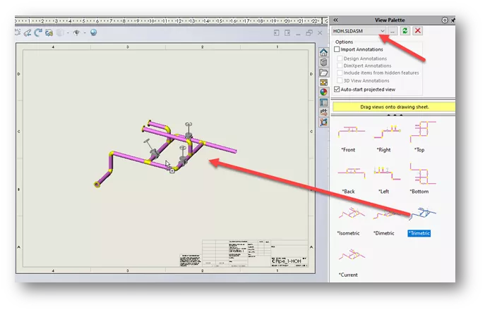
- On the Task Pane, click the View Palette tab. Use the pulldown arrow to choose the top-level assembly, or click the browse button and browse to assembly. Drag over a Trimetric view. Adjust drawing view scale as necessary.
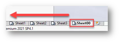
- Rename Sheet4 to Sheet00 and drag the sheet tab to a position before Sheet1.
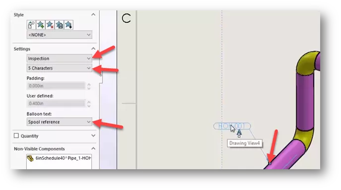
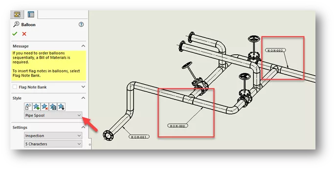
- Define the Spool Segments. From the Annotations Toolbar, select the Balloon command.
- Under Settings, choose Inspection for the Border style, set to 5 Characters, and under Balloon text, choose Spool reference.
- Click the edge of a pipe in a spool segment to place the balloon. The balloon shows the spool name.
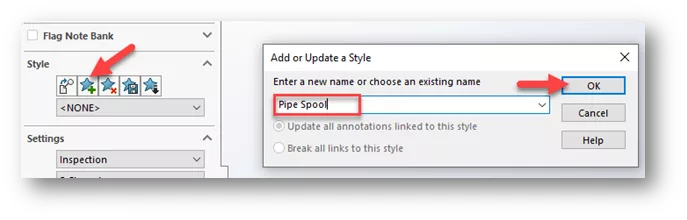
- Let's create a new Style for this balloon so we can use it again. Highlight the balloon. In the Balloon PropertyManager, under Style, click Add or update a style.
- Give the Style a name and click OK.
- We can use the new style to create additional balloons with spool names. Click the Balloon command, and under Style, use the drop-down to choose the Style we added.
- Place the additional balloons by selecting a pipe edge in each renaming spool segment. Balloons are added in the same style with each spool reference.
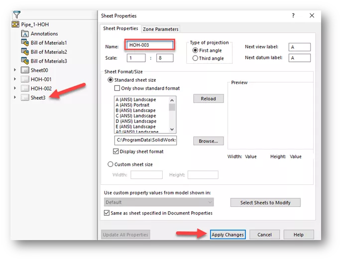
- Finally, let's rename each sheet to match the spool name. Right-click on a sheet in the Drawing PropertyManager and click Properties. Under Name, type in the name of the spool segment and click Apply Changes. Repeat for remaining sheets.
Want to become an expert?
Take the official SOLIDWORKS Routing: Piping and Tubing training course from GoEngineer.

SOLIDWORKS CAD Cheat Sheet
Our SOLIDWORKS CAD Cheat Sheet, featuring over 90 tips and tricks, will help speed up your process.
Related Articles
Learn SOLIDWORKS Online: Virtual Classroom vs. Self-paced Training
Obtaining and Using SOLIDWORKS Certification Exam Vouchers
What's New SOLIDWORKS 2022: Routing, Structure Systems, Parts & Features

About Zach Brown
Zach Brown is a certified SOLIDWORKS Expert and a Technical Support Engineer. Prior to working at GoEngineer, he spent 15 years as a mechanical designer, CAD support tech, and instructor using SOLIDWORKS. His hobbies include playing guitar, riding motorcycles, and skiing.
Get our wide array of technical resources delivered right to your inbox.
Unsubscribe at any time.