Create J-Slots in SOLIDWORKS on Cylindrical Parts
In this tutorial, see how to create J-Slots in SOLIDWORKS on cylindrical geometries. Simulating fourth axis machining operations, we will be modeling a cutting tool and its path.
Begin with a cylinder tangent to the top plane.
On the top plane, we'll create our first sketch. It includes a slot created with the Centerpoint Arc tool and a vertical line.
The vertical line orients the arc with a tangent relation and represents the straight portion of the tool path. (Figure 1) This will be the reference sketch needed for the Wrap feature required to project sketch entities onto the cylindrical face.
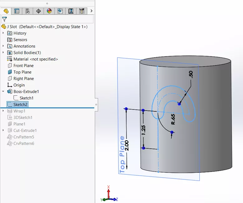
Figure 1. The sketch used to create the tool path
The Wrap feature requires a closed profile, similar to simple extrudes and revolves. To get a closed profile, convert the straight line and arc centerline of the slot (using Convert Entities), then offset both segments by 0.25 (using Offset Entities), and finally, closing the ends with straight lines. (Figure 2)
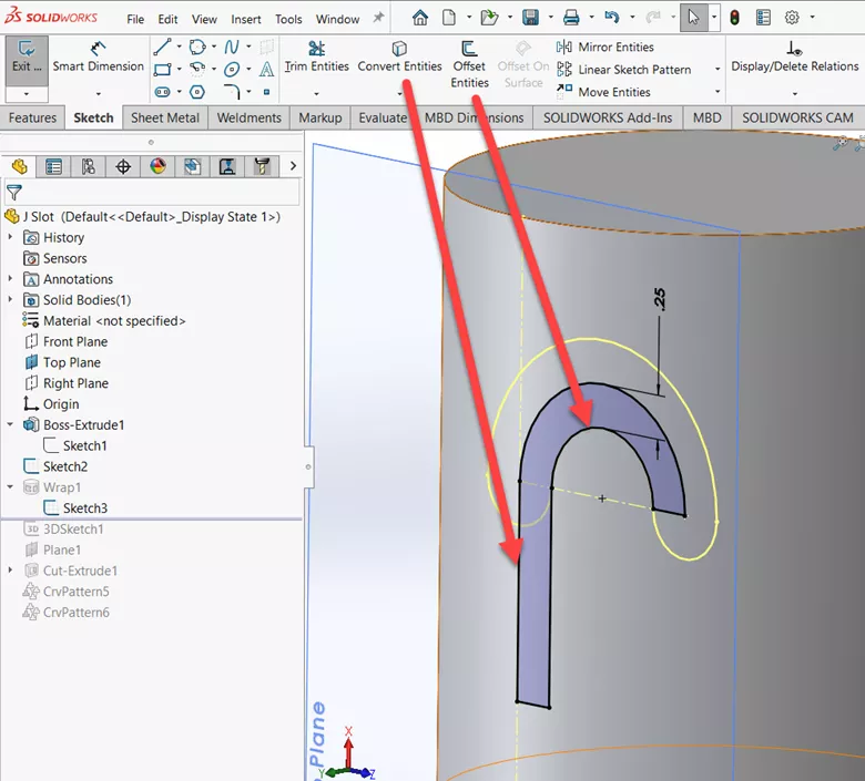
Figure 2. Closed sketch for Wrap feature
Using a Wrap feature with the Scribe option allows for the wrap sketch to be projected onto the cylindrical face in a way that it splits the face into two coincident faces. Selecting Deboos will cut into the model and selecting Emboss will generate a protrusion; neither of which is wanted here. (Figure 3)
Suggested Article >> SOLIDWORKS Wrap Feature Tutorial
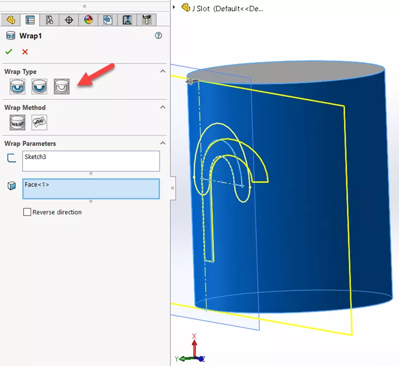
Figure 3. Wrap feature projecting a sketch onto a cylindrical face
This new face allows us the creation of the actual tool path by converting two of its perimeter edges into 3D sketch entities. To do that, create a new 3D sketch, CTRL-select the two perimeter face edges, and select Convert Entities. (Figure 4)
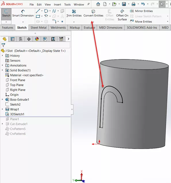
Figure 4. Converted edges in a 3D Sketch
For clarity, we’ll add a reference plane that we’ll use to sketch the tool profile on. References for the plane are the cylindrical face and the Vertex at the junction between the straight and curved portions of the tool path. (Figure 5)
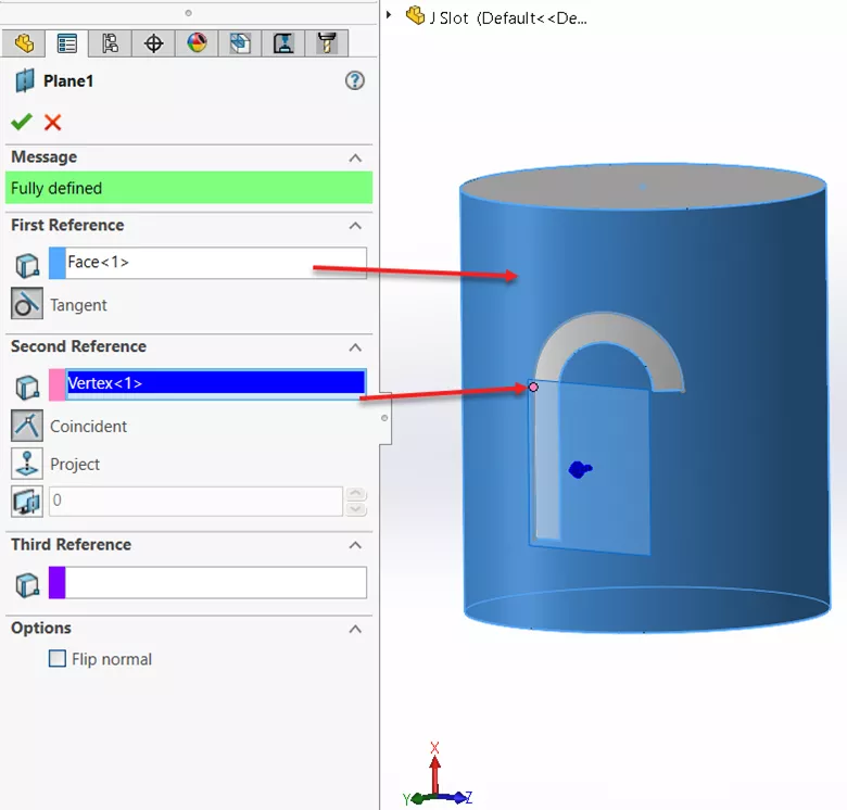
Figure 5. Reference plane for tool profile
On the new reference plane, draw the sketch for the tool profile, which is a circle centered on the same point used for the reference plane. Make a simple Cut Extrude into the model. (Figure 6)
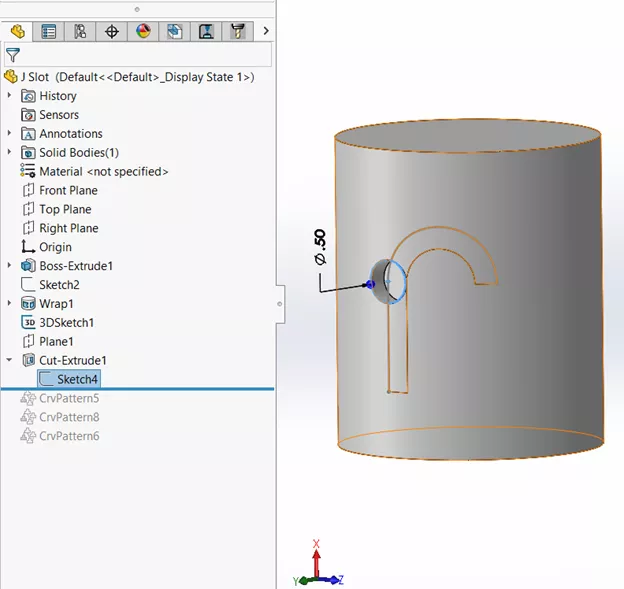
Figure 6. Tool profile cut extrude
With the tool profile cut in place, we can replicate it using a Curved Driven Pattern along the curve segment of the tool path. (Figure 7).
The important parameters for the pattern are the large number of instances, 35 in this case, and the alignment method, which is tangent to curve.
This allows us to designate the cylindrical face of the model as the face normal. This changes the angle of the cut continuously over the span of the tool path. The feature to pattern is the cut extrude. If you initially get rebuild errors, try reversing the direction of the pattern.
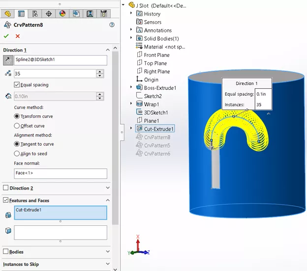
Figure 7. Curve drive pattern along the tool path curve
Now we'll do another Curved Driven Pattern, but this time pattern the cut extrude down the straight segment of the tool path. (Figure 8)
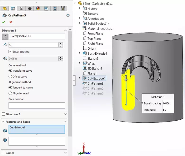
Figure 8. Curve drive pattern along the straight segment of the tool path
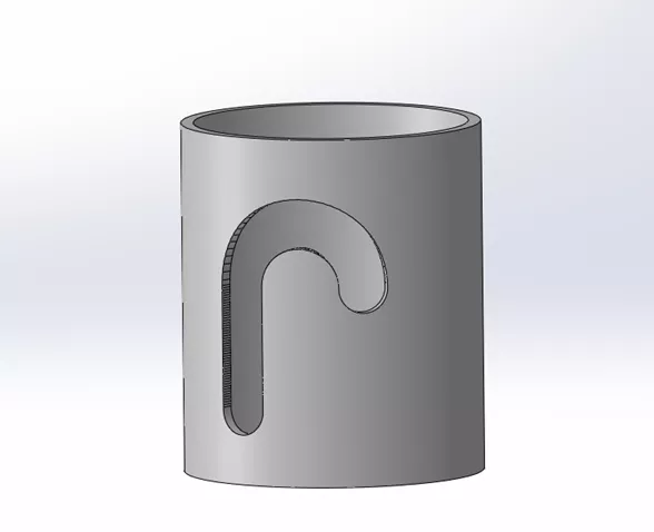
For illustration and added realism, I’ve cut out the center to create a pipe. (Figure 9)
This concludes how to create J-slots in SOLIDWORKS. I hope you found this tutorial helpful. Check out more SOLIDWORKS tutorials below.
More SOLIDWORKS Tutorials
How to Create an Extrude Cut on a Curved Surface in SOLIDWORKS
SOLIDWORKS Convert Entities Quick Tip
Create Reference Planes in SOLIDWORKS: Offset, Angle, Mid, & Cylindrical Surface
Display SOLIDWORKS Sheet Metal Surface Area in Your Bill of Materials

About Rodolfo Gutierrez
Rodolfo Gutierrez is a Mechanical Engineer by profession specializing in SOLIDWORKS, Routing, PDM, Sheet Metal, and Weldments. Lucky husband and goofy dad. Loves productivity hacks.
Get our wide array of technical resources delivered right to your inbox.
Unsubscribe at any time.