Forming on the Edge with the Forming Tool in SOLIDWORKS
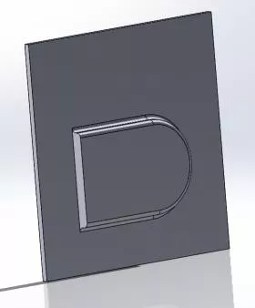
In this SOLIDWORKS tutorial, we are tasked with making an enclosure where we have formed areas on the vertical edge of the encloser, and there needs to be a clearance hole for the mounting hardware. To accomplish this, we need to make the form, create a form folder in our Design Library, save the feature in our form folder, and then accurately place the form onto the enclosure. Let’s get started.
Making the Form Tool
The first thing we did was start with a New Part file. We then drew a Center Rectangle on the Front Plane. Once it was fully defined, we extruded it 0.125” to give it some thickness. Our rectangle is bigger than our forming tool profile and has a stopping face and surface to create the form profile on.

We then drew the profile of the form shape desired and dimensioned it so that it’s fully defined (no blue lines in our sketch), and created a Boss Extrude.

Next, we added fillets to the edges of the part.
Note: We purposefully did not fillet these edges because we were adding this to the edge of the part and we are going to designate this face as one of the faces to be removed.
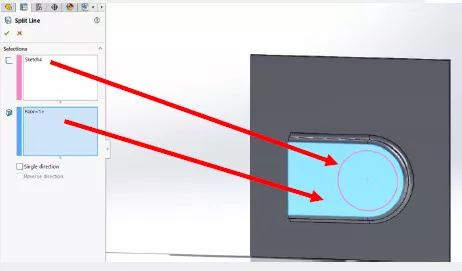
We want to have a clearance hole for a screw, so we are going to add this to the form tool design. To do this, we drew a sketch on the top face of the boss extrude. We made the circle concentric to the diameter of the form shape and made it fully defined by giving it a diameter dimension.
We then used the Split Line command to project the sketch onto the face of the boss extrude. By using the Split Line command, we project our circular sketch onto the top face of the boss extrude we made earlier. This splits the face to having two defined areas the profiles of the form and the profile of the circle, this will be needed in the next step.
Forming Tool and Feature Settings
We then went to the sheet metal tab and clicked on the Forming tool command.
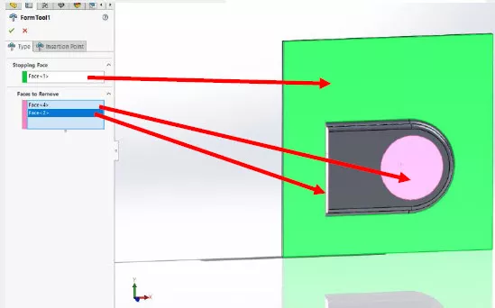
The FormTool FeatureManger is asking for a couple of things: Stopping Face, Faces to Remove, and the Insertion Point.
In the Stopping Face box, pick the face of the baseplate we created. This is the face the forming tool will use to mate to the face of the main part we apply the forming tool to.
For the Faces to Remove, click on the inside of the split line circle and the face that we are placing on the edge on the sheet metal part we want to form.
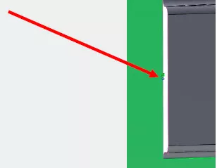
The next step is to set an insertion point. I picked a point on the midpoint. This is an important step as it will allow us to align the form tool to the edge of the part we are forming.
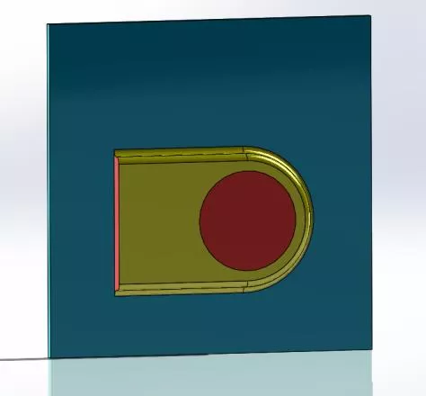
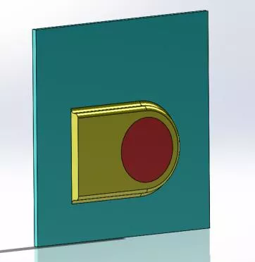
When you have picked all your faces and defined your insertion point, hit the green checkmark (OK) and your part should look like this. Just to review, the blue face is the stopping face, the yellow is the area where the material is being formed, and the red/pink area is the area where the material will be removed when we apply the form to the enclosure. Now let’s save the files.
Saving your files
The recommended method for saving your form tool is to save it into your library giving you quick, easy access. The two file types we are focused on are
PART FILE: *.SLDPRT. This is a standard SOLIDWORKS part file. FORMING: *.SLDFPT This is the filetype that we will use to save the forming tool in our library.
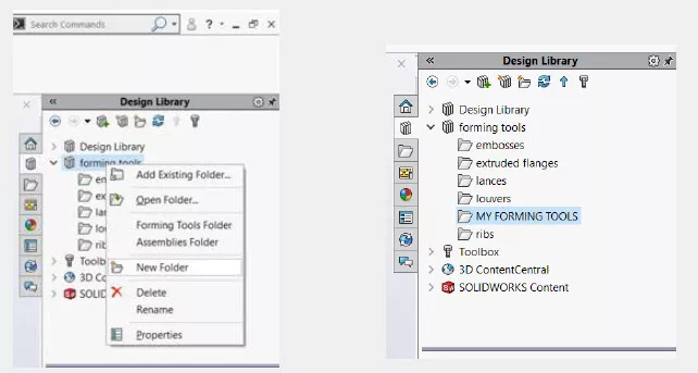
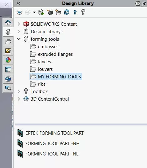
Let’s start by creating a forming folder in the Design Library:
- It is important that you create your forming tool folder under the forming tools library.
- Start this by expanding the forming tools folder.
- Using the right mouse button, click on forming tools.
- In the drop-down menu, click on New Folder.
- Name the folder, in this case, something you can easily recognize. I named mine “MY FORMING TOOLS”. See images below.
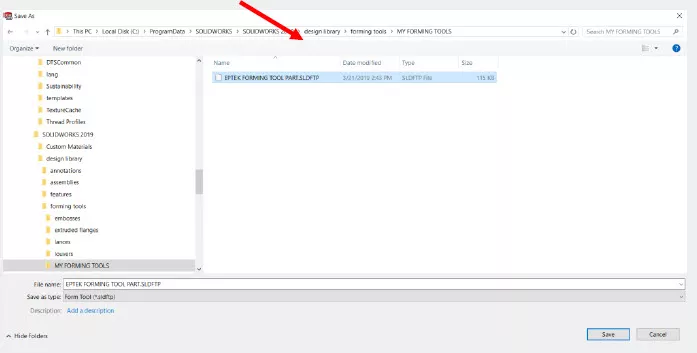
Now that we have our forming tools folder, we need to save the part and the forming tool in the folder we just created. Click File > Save As and Save the forming folder you just created. The name of the forming tool in this example is: EPTEK FORMING TOOL PART.sldftp. Again, it is saved into design library>forming tools> MY FORMING TOOLS.
Apply the forming tool to the enclosure
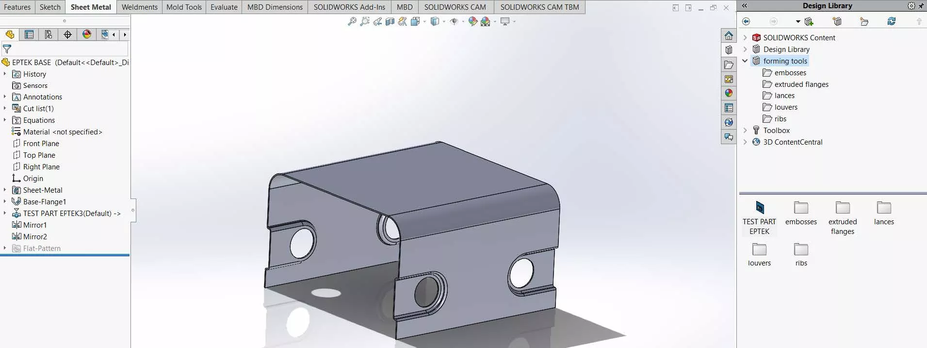
We now need to apply the form to the enclosure. In the image below, we opened the enclosure file, and over on the right of your screen, the Design Library is expanded so you can see the form tool we just created (see image below).
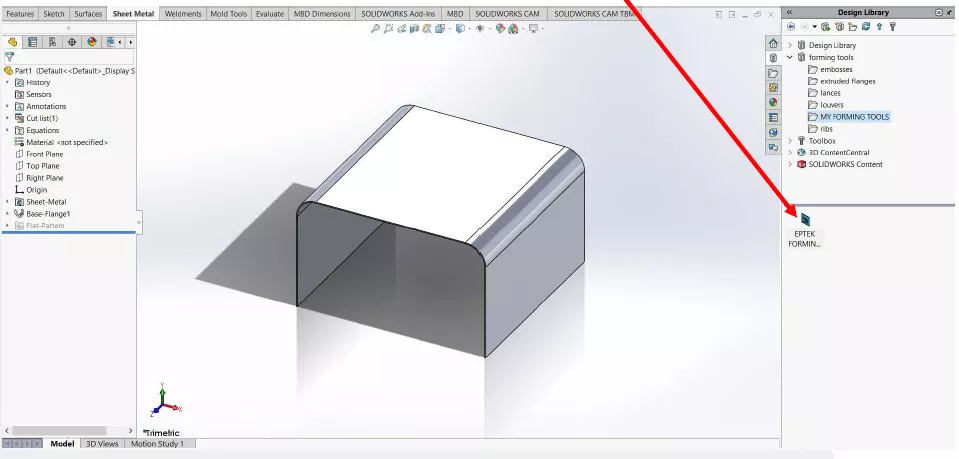
Drag and Drop
Using your mouse, left-click and hold down (DO NOT LET GO YET) on the file EPTEK FORMING TOOL PART.sldftp in your library and drag the file onto the main body. Let go of the left mouse button once the forming tool file is on the correct face you want the forming tool to be applied to. The forming tool is yellow because we have not defined the final location.
The face of the main body we are applying the form to is blue and the form itself is yellow If you need to adjust the angle do so using the Rotation Angle.
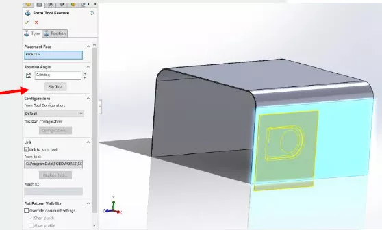
The next step is to set the position. To do this, click on the Position Tab at the top of the Form Tool FeatureManager.
Click on the blue dot with the left mouse button and hold it to drag and drop the insertion point of the forming tool onto the vertical edge of the main body. This will align the edge of the form tool to the edge of the main body.
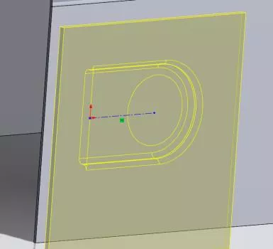
*If you have a pencil following your mouse you will need to hit escape before dragging and dropping the location point.
Next, add a dimension to set the vertical height. Once you do this, the blue lines will turn black; we now have a fully defined location.
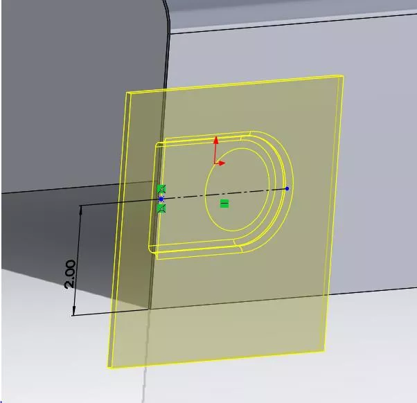
Hit the green checkmark or OK and you should have a part that looks like this below.
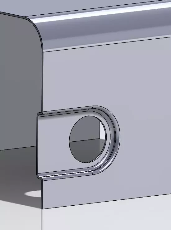
Notice that all of the red areas that we defined in our forming tool; those areas are gone. The yellow area is the area where the material was formed to the shape we defined and the stopping face. We can use the Mirror command to add these to all 4 vertical Edges of the part if so desired.
What happens if…
What would happen if we did not select the vertical edge on the forming tool as Faces to Remove, the form would look like this.
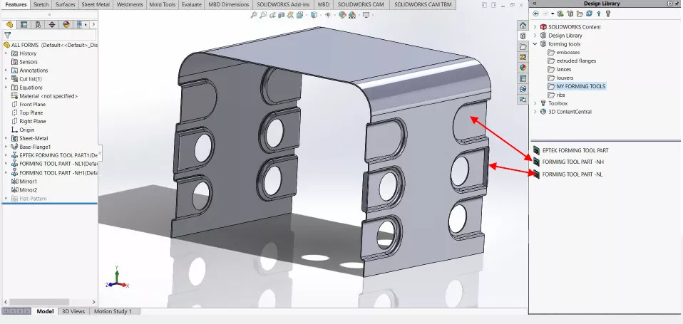
I saved the form into MY FORMING TOOLS folder and named the file: FORMING TOOL PART-NL (No Lip) repeating the steps from earlier and I also created a third Forming Tool FORMING TOOL PART-NH (No Hole)
The image below shows all three of the forming tools:
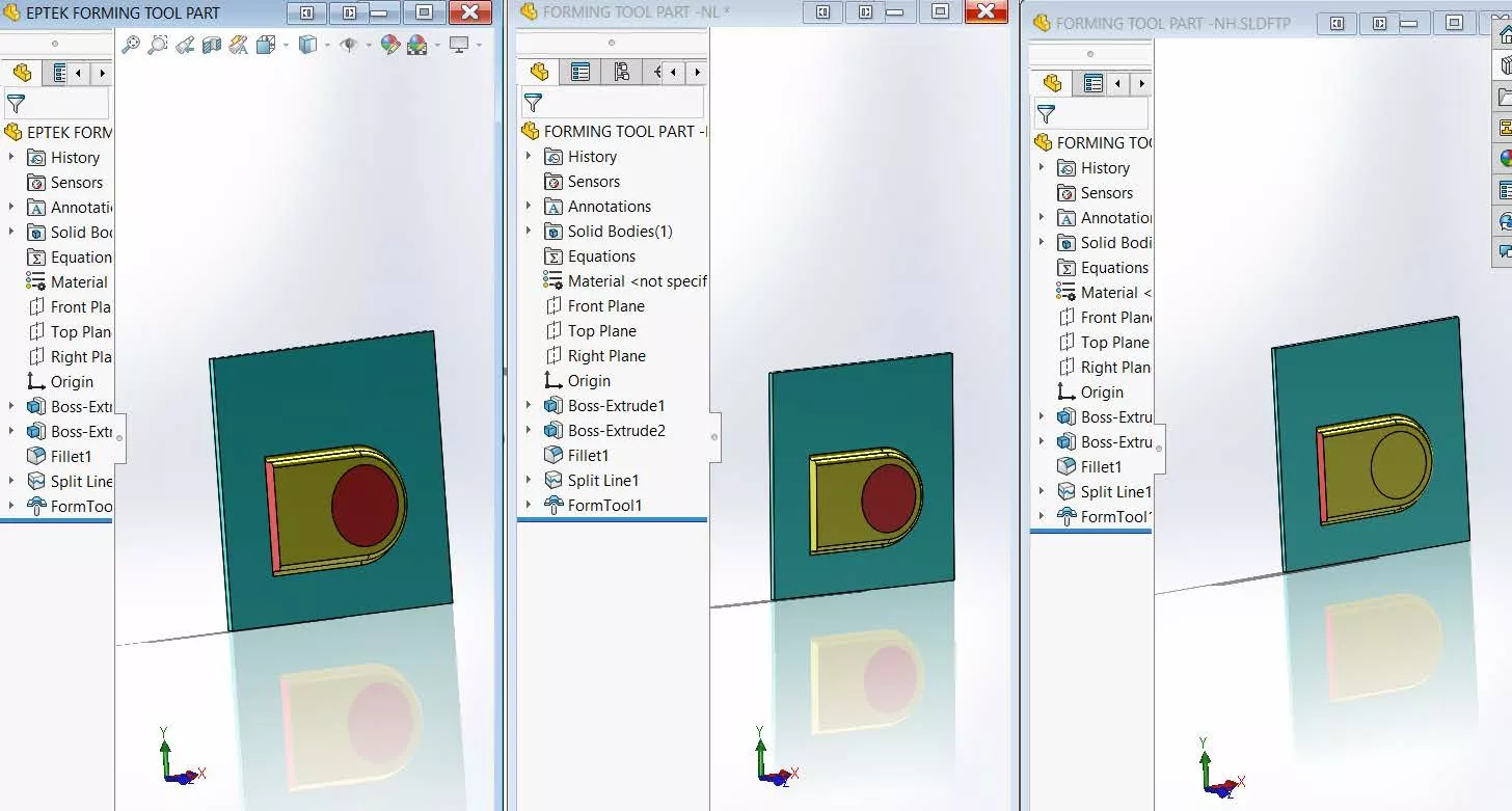
We applied each of the forming tools to the enclosure the result would be three distinct shapes that showed the different displacements of material as well as the faces that were/were not removed.
More SOLIDWORKS Tutorials
SOLIDWORKS Copy and Paste Features: Same or Different Parts
SOLIDWORKS Routing 101: Pipe Design
SOLIDWORKS Convert to Sheet Metal Command Explained
How to Create a Lip/Groove Feature in SOLIDWORKS
Scanto3D Add-in Explained: Activation, Wizards, and Tutorial

About David Cersley
David has been using SOLIDWORKS since 2005 across multiple industries most notably Golf Club Design. He owned and operated a successful design and consulting company that used SOLIDWORKS to bring napkin sketches to production. The industries he's been a part of range from Medical, Aquaponics, Forging, CNC Shops, Roto-Molding factories. He is a proud father to daughter Emmaline (8) and is a husband of 19 years. He is a two-time Ironman finisher and recently qualified for the Boston Marathon.
Get our wide array of technical resources delivered right to your inbox.
Unsubscribe at any time.