Managing SOLIDWORKS Loft Connectors
In SOLIDWORKS, a Loft feature creates a solid or surface by making transitions between sketch profiles. A Loft can be a base, boss, cut, or surface.
Create a loft using two or more profiles. Only the first, last, or first and last profiles can be points. All sketch entities, including guide curves and profiles, can be contained in a single 3D sketch.
For a solid loft, the first and last profiles must be model faces or faces created by split lines, planar profiles, or surfaces.
There are several ways to manipulate, edit, and view lofts.
In this article, we will look at SOLIDWORKS Loft connectors and their effect on the resulting Loft. Sometimes it will still be necessary to create guide curves, but working with the connectors first may eliminate that.
Additional functionality for Lofts can be explored through the SOLIDWORKS help menus. Also, don’t forget to use the context help in the Loft PropertyManager (the question mark in the upper right of the PropertyManager).
SOLIDWORKS Loft Connectors
Loft connectors are generated in the Loft feature when the profiles are selected. You will see the primary connector points displayed in green. The place you select in each profile will determine the primary connectors. Depending upon where the profiles were selected, the connectors can introduce unintended twists or deformed faces.
How to Use the Connectors
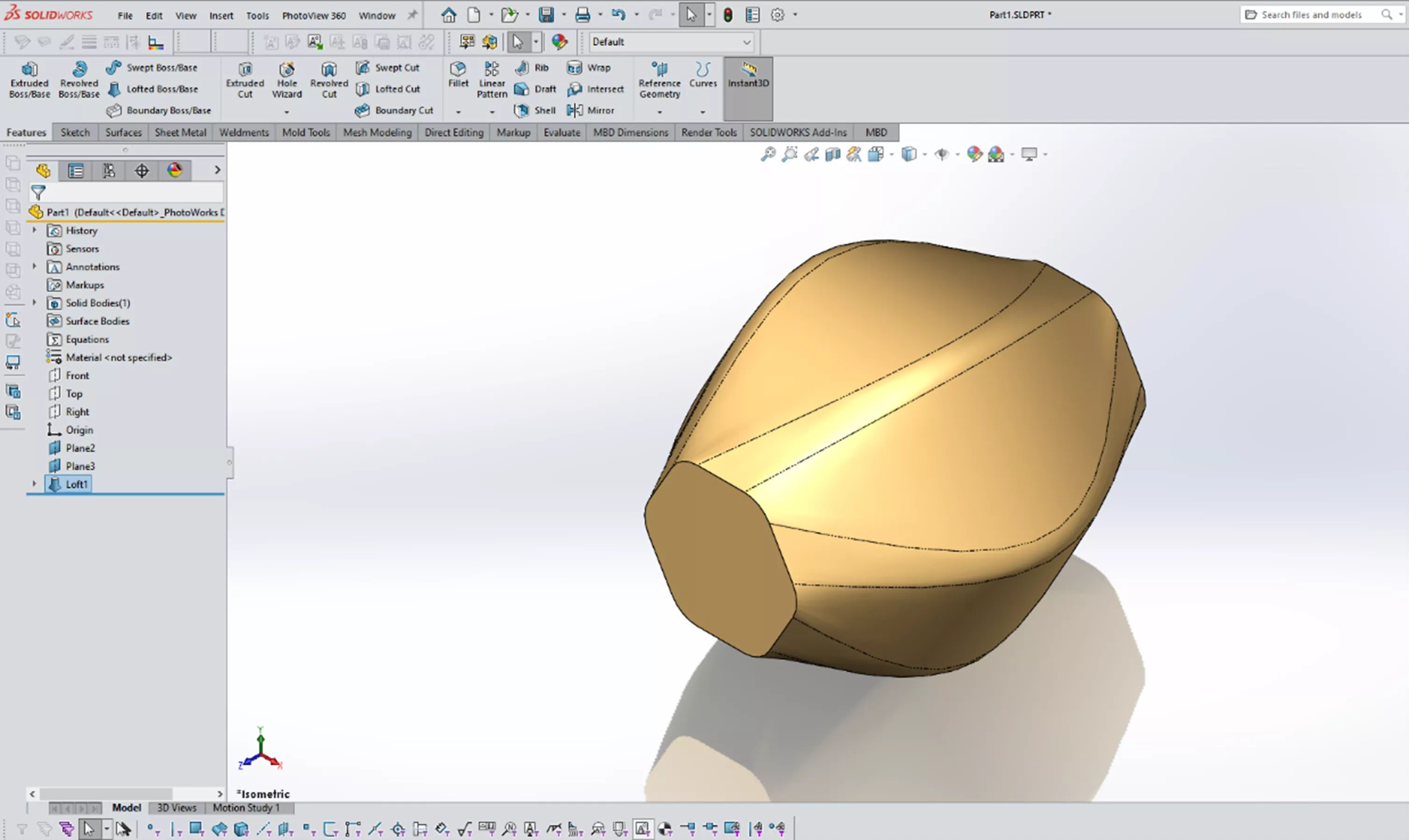
Connector points can be moved with a simple click and drag. Here I have a three-profile Loft feature where I have intentionally selected the profiles in different locations. This results in the connectors being placed in positions that generate a loft with some undesirable alignment.
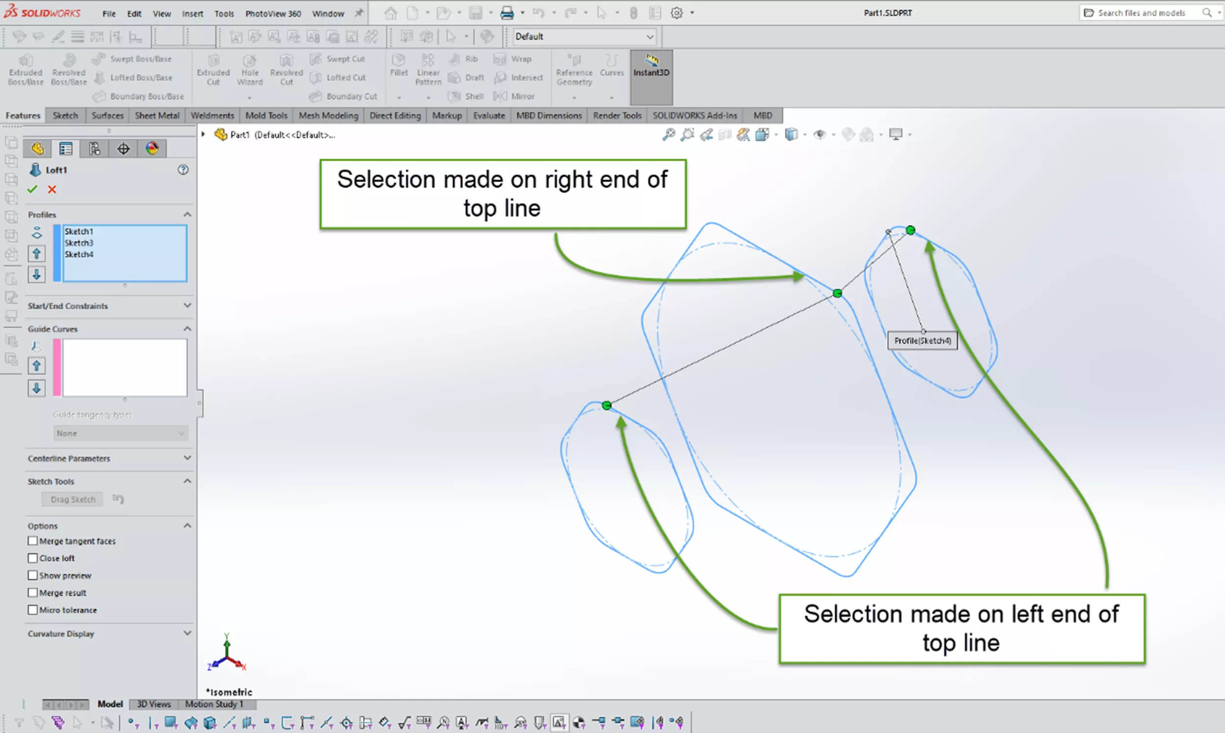
This results in a skewed alignment.
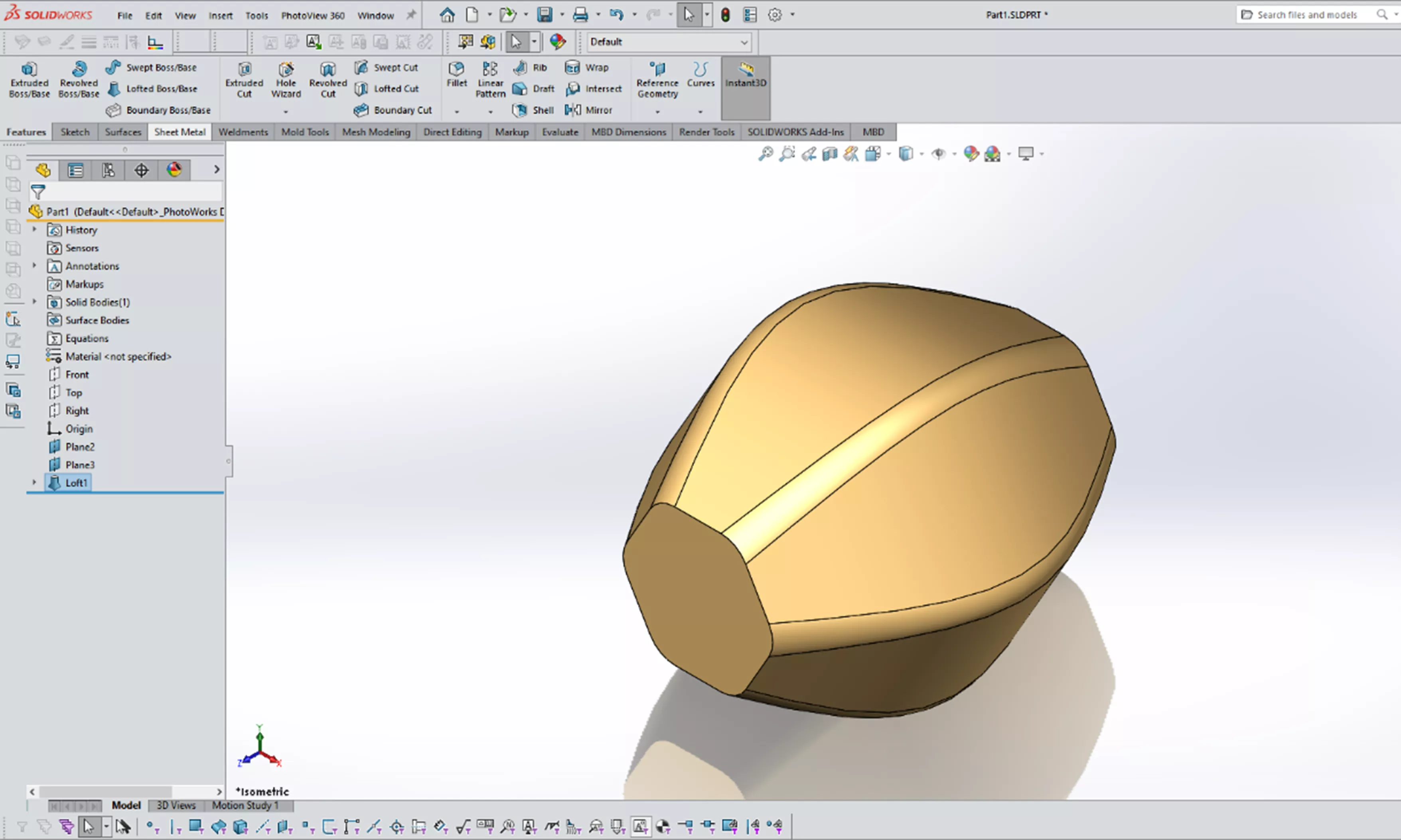
By editing the Loft feature, we can correct our selections. Dragging the connector in the center profile to a position on the other end of the line resolves this.
In some situations, the connector that needs adjustment is not primary. Using the RMB (Right-Mouse-Button) in the graphics area displays additional options.
Show all connectors
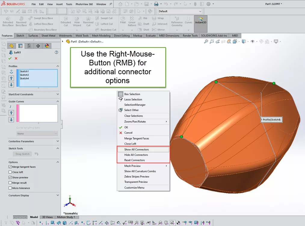
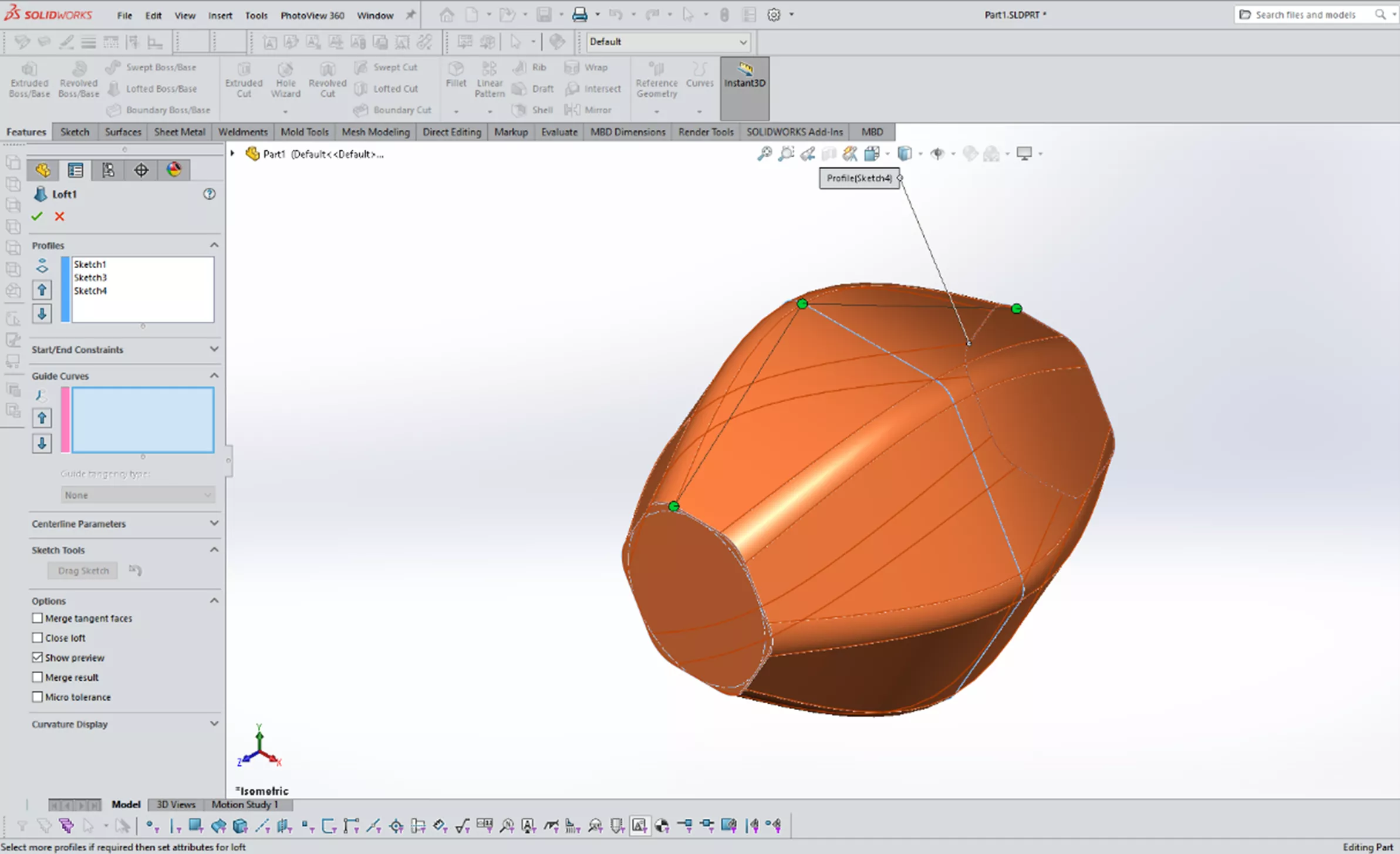
This option will display all the connection points being considered. These points are displayed in blue.
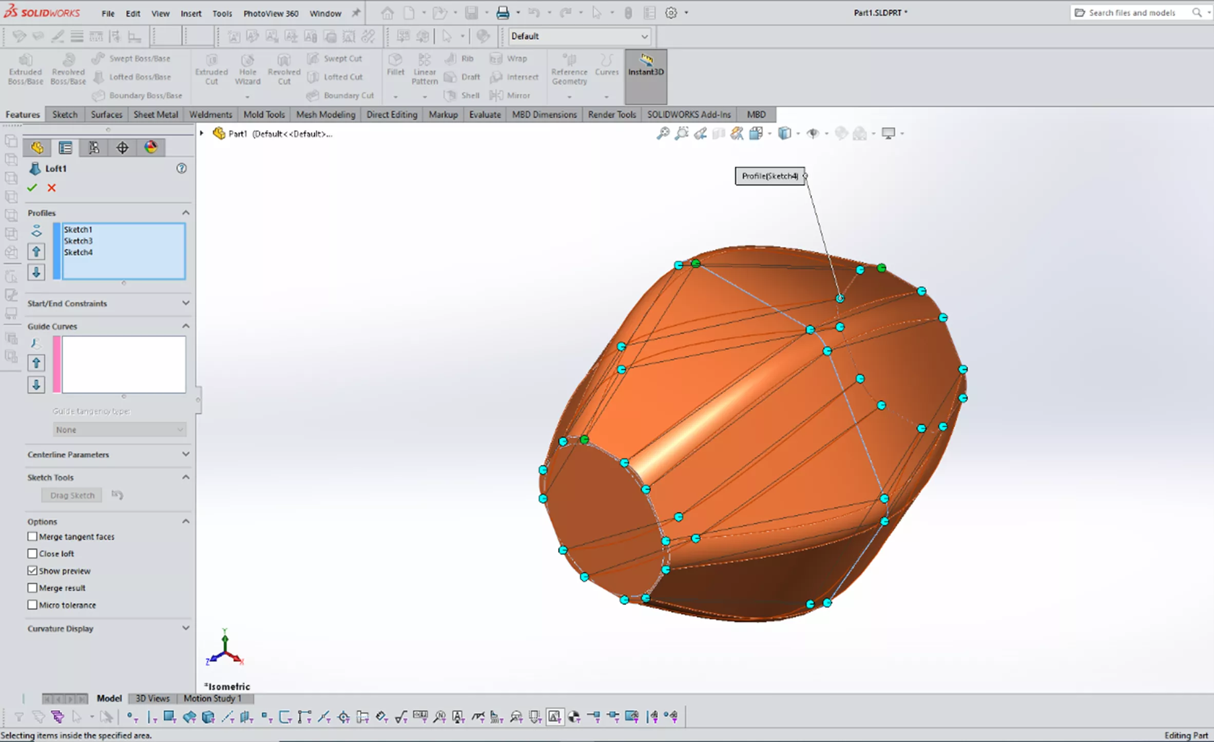
With these connectors now visible, you can further refine your loft shape. When dragging one of these connectors (e.g., off an end point), a new connector is also placed in that location. Using this process, you can affect the resulting face creation.
Hide all connectors
This does what it implies - hides all the displayed connectors. With all connectors displayed, there are times when it is difficult to see the model preview clearly.
Reset connectors
If you need to start the connector refinement over, you can rest the connectors to their defaults.
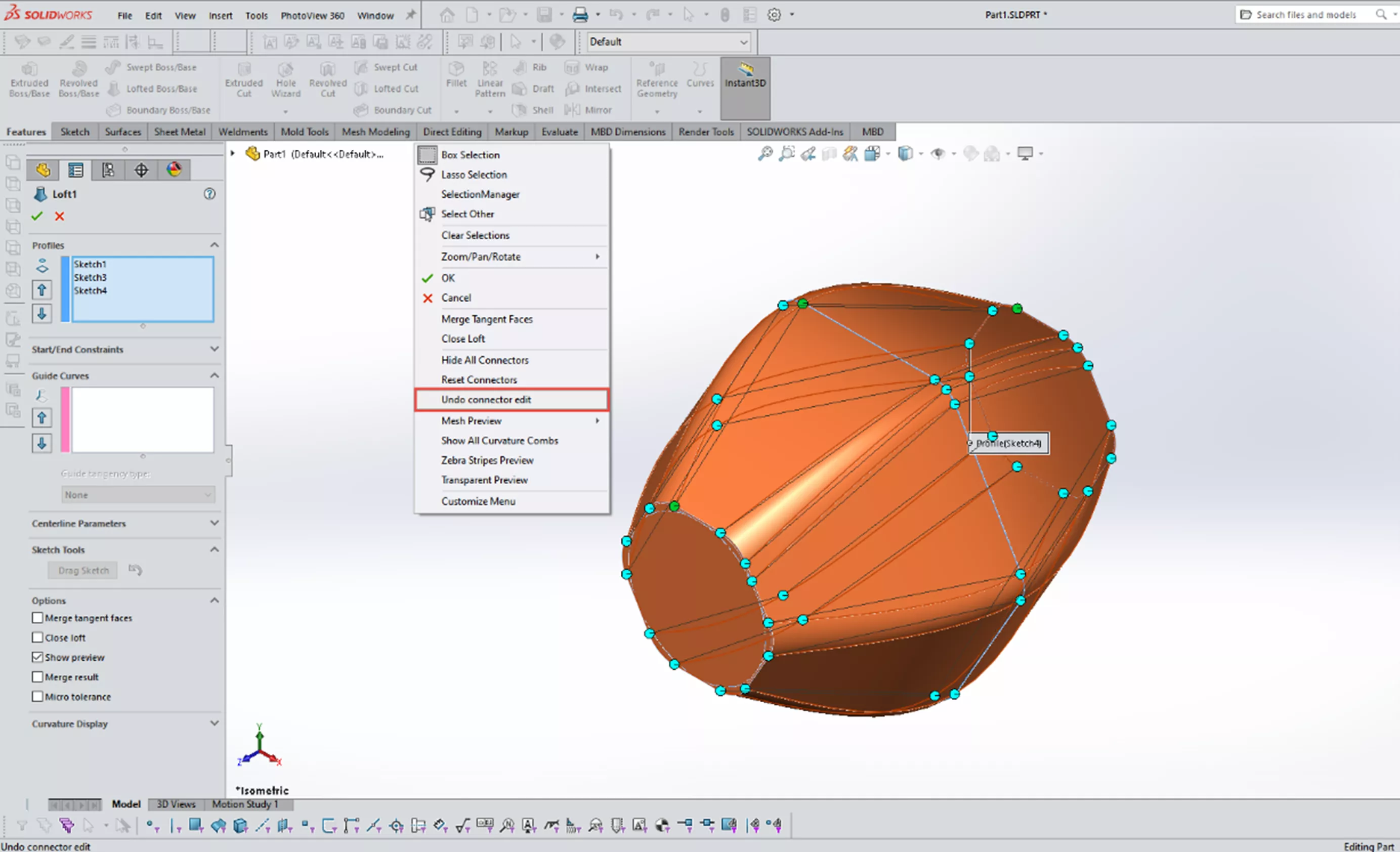
Undo connector edit
If you would like to back up a few steps, use the undo connector edit option in the popup menu using the RMB (Right-Mouse-Button).
As mentioned above, the context sensitive help access is always there for you. Use it rather than struggle with the inputs and how they work.
I hope you found this article helpful. Check out more SOLIDWORKS tutorials below.
More SOLIDWORKS Tutorials
How to Create an Extrude-Cut on a Curved Surface in SOLIDWORKS
Insights of SOLIDWORKS Surfacing: Tips & Tricks
3 SOLIDWORKS Surfacing Tools to Try
Creating a Non-Circular Helix in SOLIDWORKS with Surfacing Commands
![]()
About Martin Adams
Martin Adams is a Senior Technical Support Engineer at GoEngineer supporting SOLIDWORKS CAD and SOLIDWORKS Electrical products. In addition to a CSWE certification, he has a Bachelor's degree in Industrial Engineering and an Electrical Associate's degree. Prior to joining GoEngineer in 2019, he worked for almost twenty years on prototype automotive instrumentation. He also served as an Electrician's Mate in the US Navy. His favorite activities are fishing and spending time around a campfire with friends.
Get our wide array of technical resources delivered right to your inbox.
Unsubscribe at any time.