Insights of SOLIDWORKS Surfacing: Tips & Tricks
What is a surface? To understand what a surface is we must understand what a solid is. In a solid body, every edge is a boundary between two faces, which creates a watertight, enclosed volume that can contain mass. So that means that conversely, a surface body will have edges that bound only one face, leaving an open model with an open volume. The edges of a solid will be black while the edges of a surface will be blue. In this blog, we'll go over everything you should know about SOLIDWORKS Surfacing.
![]() Related Video: SOLIDWORKS - Surfacing Basics
Related Video: SOLIDWORKS - Surfacing Basics
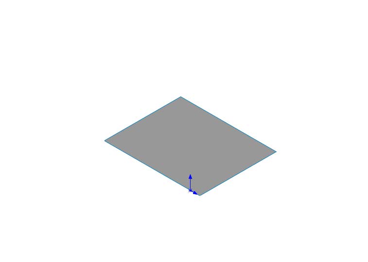
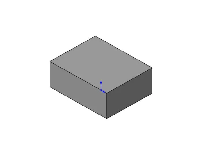
Figure 1: Surface Face Figure 2: Solid Faces
Parameterization of surface faces
All surfaces in SOLIDWORKS are defined by a U-V curve mesh that can be seen with:
- Face Curves
- Dome
- Fill Surface
- Boundary Surface
- Freeform
- Loft
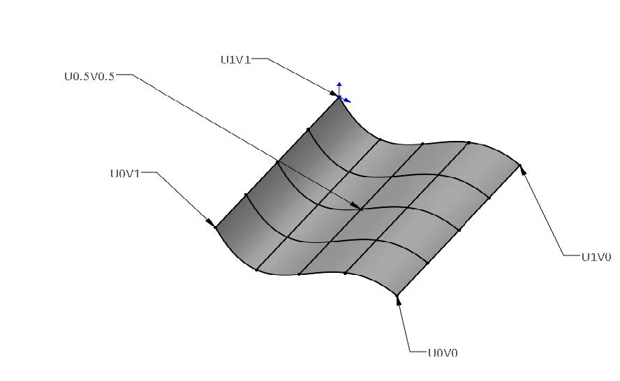
Figure 3: U-V Parametrization
The mesh will always have perpendicular curves, however, not all shapes are four sided. The software will typically trim a four-sided surface to create a three-sided shape. Also, if one or more of the sides is of zero length, the curves in that direction intersect at a point called a singularity. This is called a degenerate surface and can cause problems at a solid level.
Algebraic Surface
U-V curves on algebraic surfaces are straight lines, arcs, or circles. Pyramids, cubes, spheres, and cylinders are great examples.
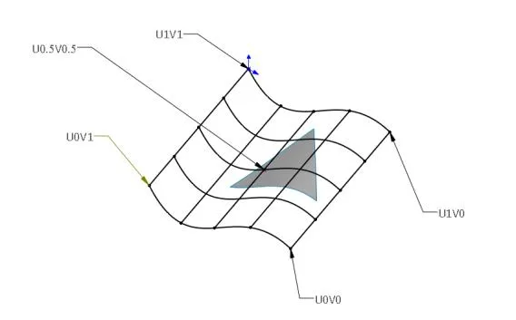
Figure 4: 3-Sided Cutout
Ruled
A ruled surface is a surface where every point on a surface has a straight line that passes through it and lies on the surface.
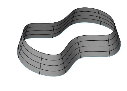
Figure 5: Ruled Surface
Developable Surface
A developable surface is a subset of a ruled surface that can be flattened without stretching the surface. Often planar, conical, and cylindrical and is the only type of surface able to flattened in sheet metal as well.
NURBS
(Non-Uniform Rational B-Spline) is a surfacing technology where the surface is interpolated between parameterized splines instead of other algebraic shapes.
Tech tip: Algebraic, ruled and developable surfaces are sometimes referred to as analytical surfaces. NURBS surfaces are often called algorithmic surfaces.
Why Use Surfaces in SOLIDWORKS?
There are three main reasons to use surfacing:
- Some shapes cannot be created with solids
- Surfaces build a shape, one face at a time
- Surfaces as reference geometry
Some shapes cannot be created with solids
This video explains how the dome feature cannot be created on the flat end of the loft, rather the filled surface with continuous continuity would cap off the flat end to make it round. Most solid geometry will create a flat face, so surfacing modeling can help us cap off flat ends or create non-planar geometry.
Surfaces build a shape, one face at a time
Surfacing allows for control of every individual face of an object, instead of building several sides at once in a single direction. This allows for the creation of organic and non-algebraic shapes in multiple directions but should only be used if that is the design intent.
Typically, hybrid modeling is preferred over just surface modeling, as many of the sides of an object can flow from a single direction with most geometry, with a particular face or subset of faces that can be individually manipulated within the context of the solid boundary. Below are some examples of how SOLIDWORKS utilizes hybrid modeling with these techniques:
- Replace Face
- Up to Surface end condition
- Using a surface to cut or sculpt
- Using a surface to split a body into multiple bodies
Surfaces as reference geometry
Many times a plane, axis, or point is not enough reference geometry to manipulate geometry from a reference. It often helps to create a reference surface to manipulate a solid model. In the model below, the reference surface is being used to change the face of the rod so that it may fit better on its reference geometry. See this video for more insight.
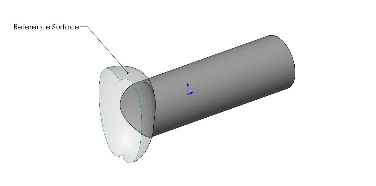
Figure 6: Surface as Reference Geometry
SOLIDWORKS Surfacing Continuity:
Please see the below links from our resource center to further explain the continuity and curvature of surfaces:
- Continuity and Curvature in SOLIDWORKS (Part 1)
- Continuity and Curvature in SOLIDWORKS (Part 2)
- Continuity and Curvature in SOLIDWORKS (Part 3)
Good Surface Techniques:
Some key techniques to keep in mind when surfacing modeling:
- Identify functional faces and symmetry
- Organize your feature tree
- Use Check Entity
- Verification on Rebuild
- Clean up
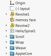
Figure 7
Identify Functional Faces and Symmetry
Getting started on complex shapes without any flat faces can be difficult. Try to utilize the symmetry about the part as much as possible by tracing sketch pictures positioned around the origin. If the part has the front or right plane bisecting in the center of the object, it will be an easier mate in an assembly and make modeling easier. See the example below for reference. To create the door handle, I have used the right plane to create one half of the model. By projecting the right and top plane sketches I can loft from the right plane sketch to the projected curve to create my complex shape easier. If you can, use flat faces or algebraic shapes to sketch on in order to leverage changes and additions as you would with a solid model.
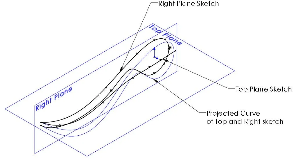
Figure 8: Positioning
Organize the feature tree
Surface modeling allows us to create objects once face at a time and as a result, surfaces often can produce a large feature tree. Many features you are building on this face by face basis are related to a particular area of the model. Try to organize each area of the model with related features in a folder so that it’s easier to make necessary changes and make the feature tree manageable. You can simply right-click on a feature to add to a folder and drag and drop features in and out accordingly.
Use Check Entity
To access the Check Entity tool, go to Tools > Check Entity or select it from the Evaluate tab in the command manager. This tool will allow the user to identify geometry issues that can cause a feature to fail for what may seem like no apparent reason. The tool will help users find open surface edges that may prevent a surface from knitting to a solid or short edges and minimum radii that may prevent shelling on a solid. A good practice is to use this tool to evaluate after creating several surface features. Surface features are built face by face and are not subjected to the same rigorous checking verification that solid features experience.
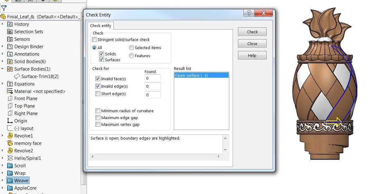
Figure 9: Check Entity
Verification on rebuild
Verification on rebuild is another excellent tool that is recommended when creating surfaces. It can be found under Tools > Options> Performance > Verification on Rebuild. Only check this option when working on surface models. This tool increases the level of error checking by running a check on every new or changed feature against all existing faces and edges, not just the adjacent faces and edges. Features with invalid geometry will fail with this option checked. Why only with surfaces? This option makes modeling more CPU intensive and can slow down performance and applies to all open documents since it is located as a system wide option. Be sure to turn this option off when you are done surfacing.
Force Rebuild (CRTL+Q) = Rebuilds all the features in a model
Rebuild (CRTL+B) = Rebuilds only new or changed features and associated child features.
Clean up
Cleaning the model is optional but can help with good “housekeeping” practices. Use Delete Bodies to delete leftover surface or solid bodies. It converts those bodies into a feature on the tree that can be suppressed, edited, or deleted later if those features need to be accessed for later revisions.
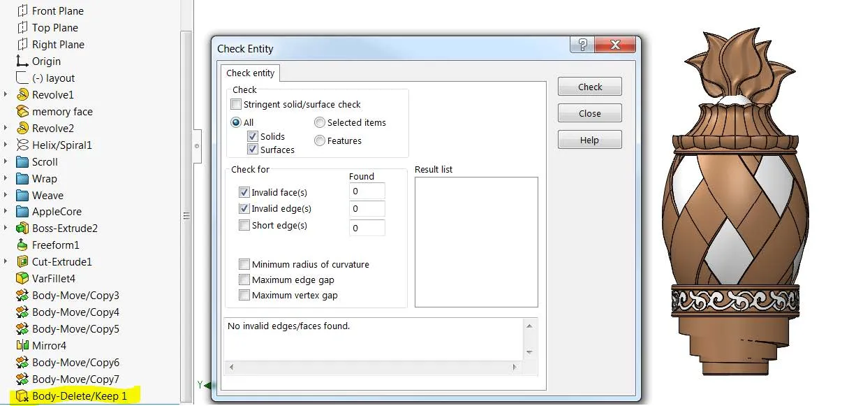
Figure 10: Clean Up
I hope you found this SOLIDWORKS Surfacing blog helpful. For more tips and tricks, check out our latest articles below.
Our Latest SOLIDWORKS Tips & Tricks
Using the Move/Copy Body Feature in SOLIDWORKS
Searching for Functions in SOLIDWORKS 2021
How to Install and Troubleshoot Fonts in SOLIDWORKS

About Jacob Bakovsky
Jacob is a Senior Elite Application Engineer at GoEngineer. His expertise is in SOLIDWORKS but he also has knowledge with PDM, Composer, Inspection, Visualize, Simulation, and the 3DEXPERIENCE platform. In addition, he also helps run the 3D printing service bureau at our Santa Ana, California branch.
Get our wide array of technical resources delivered right to your inbox.
Unsubscribe at any time.