SOLIDWORKS Configuration Publisher: Custom Dropdown Menus
In this guide, we go further in-depth using SOLIDWORKS Configuration Publisher to create custom dropdown menus for configurations when we place a component into an assembly. In part one, SOLIDWORKS Configuration Publisher: Create Configuration Tables, we learned how to create a configuration table and multiple configurations. Now we will use the configurations we created to create a design table and use Configuration Publisher.
If we recall from part one, we have a control arm with eight (8) different configurations - four (4) different angles and two (2) different lengths for one of the arms. We also created a configuration table (shown below).
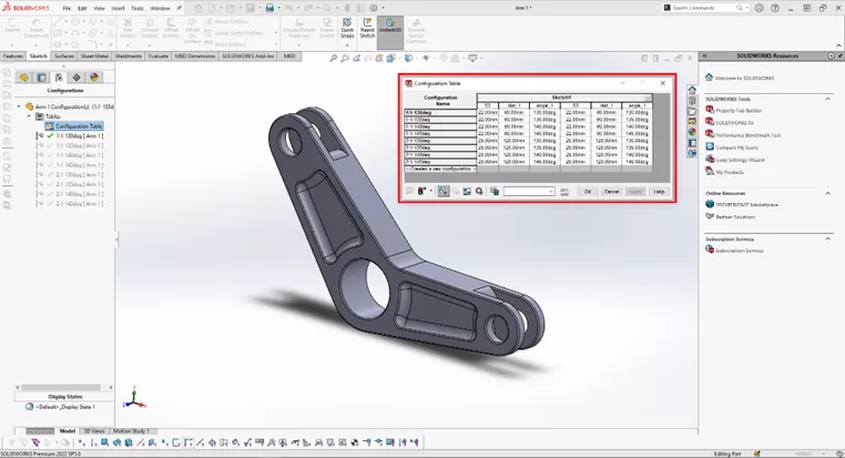
For Configuration Publisher to work properly, we need to have a design table. Now, from here, we could go straight to Configuration Publisher by right-clicking on the component name at the top of the ConfigurationManager tree and selecting Configuration Publisher. This would automatically create a design table (shown below).
In this exercise, we want more control over the design table, so we will create a design table before using Configuration Publisher.
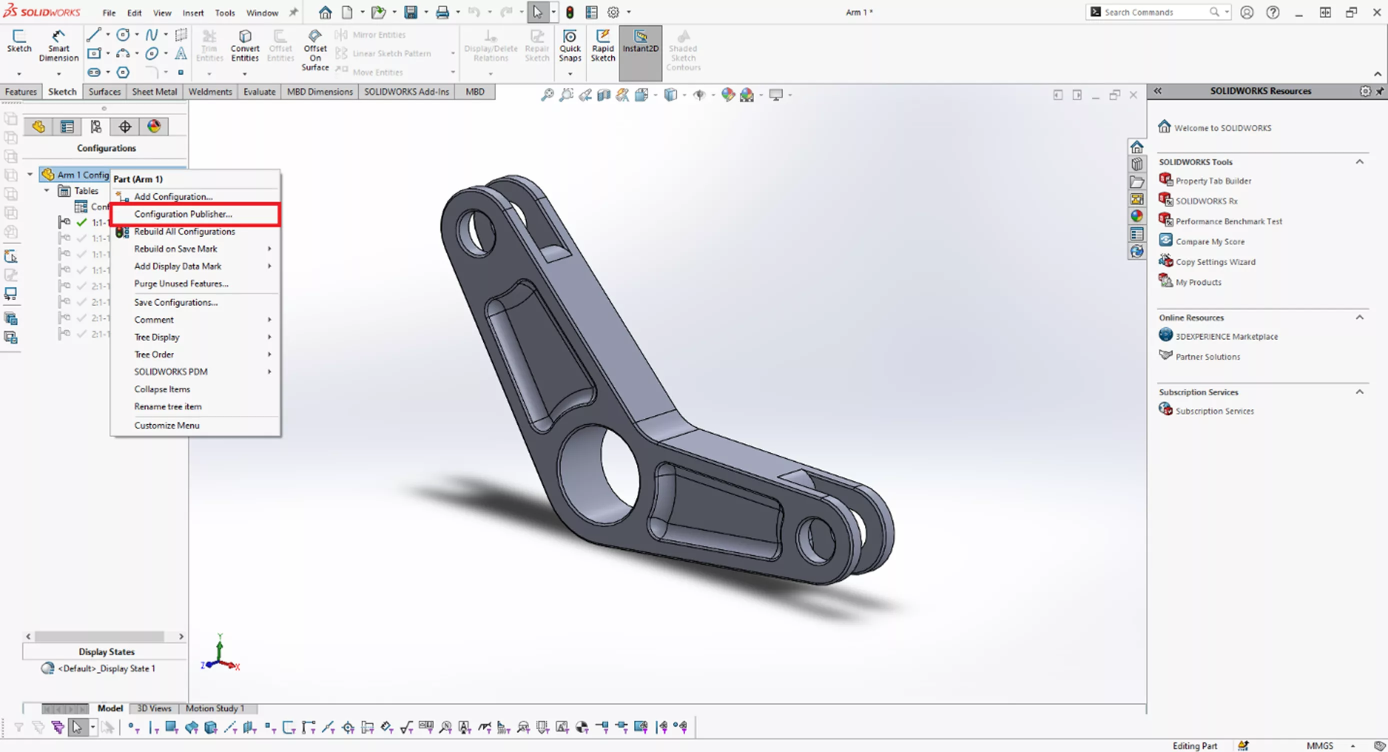
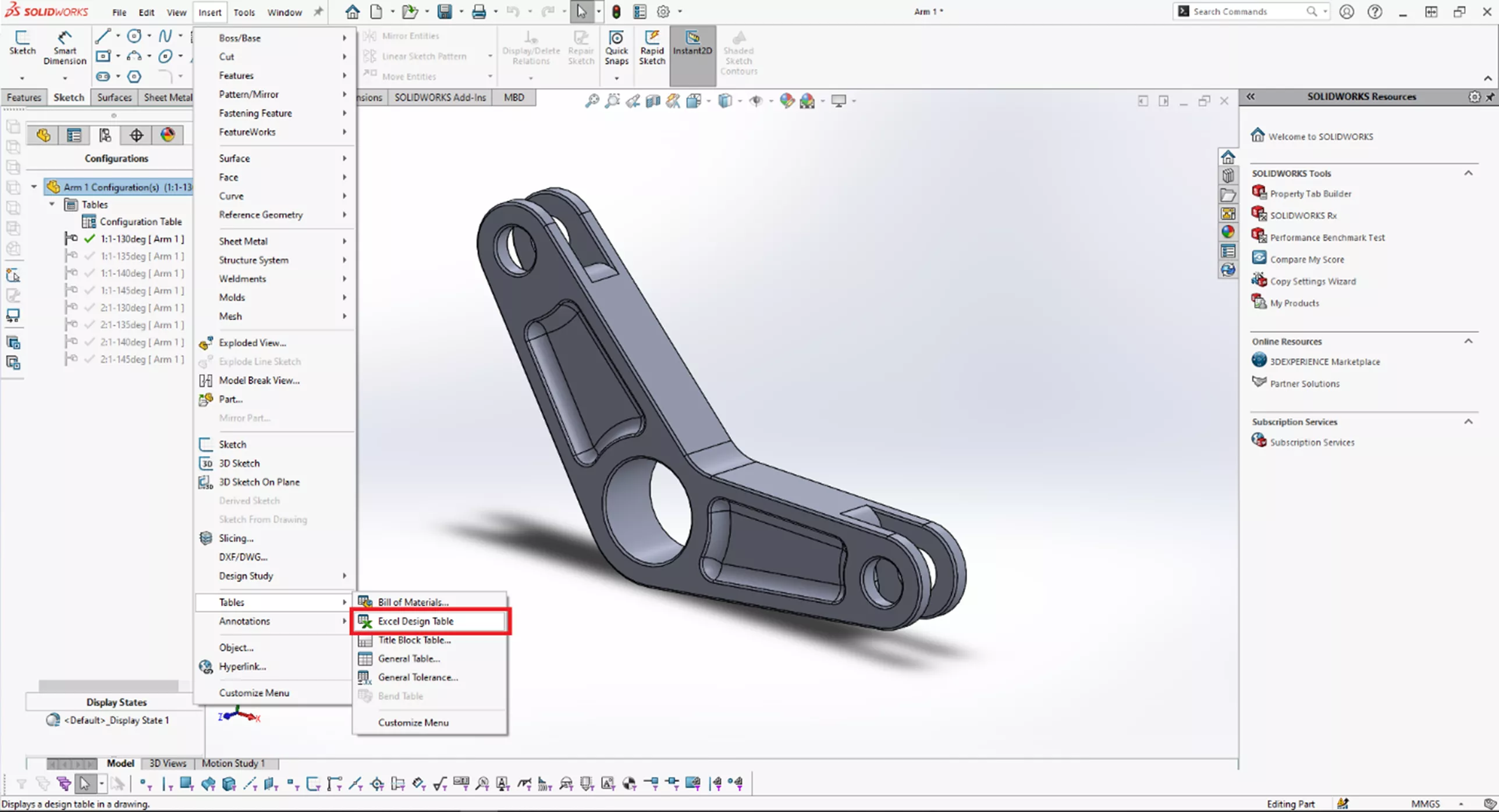
To do so, go to Tools > Tables > select Excel Design Table.
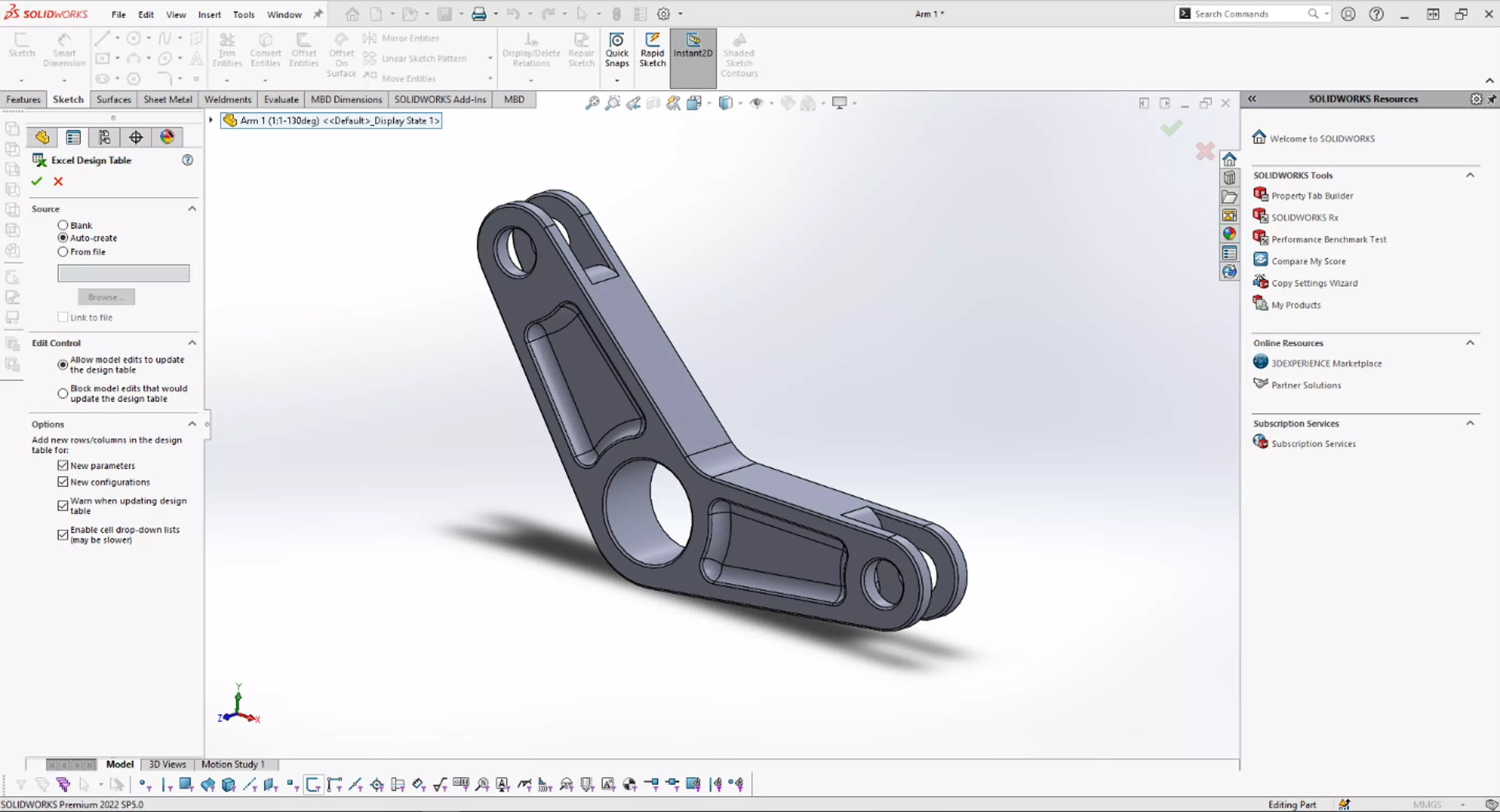
This will provide some options for creating a design table. We will allow SOLIDWORKS to auto-create the design table; select the green checkmark.
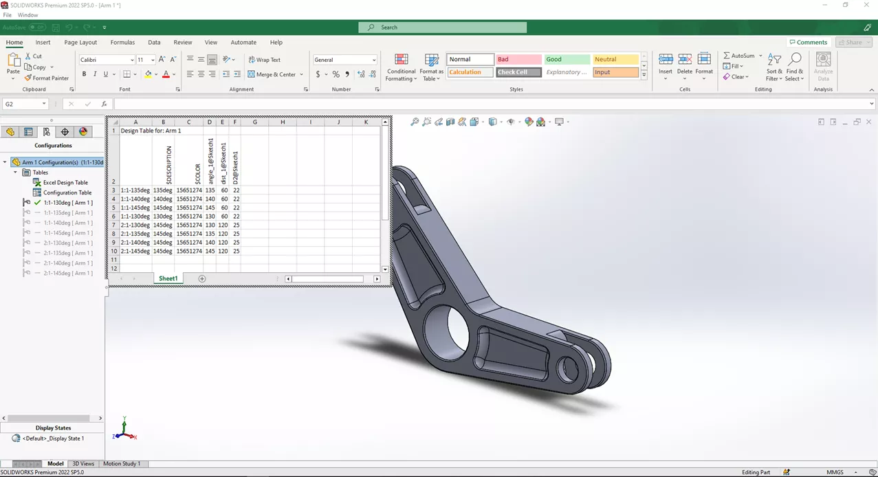
All of the configurations are listed neatly in the table. In this guide, we won’t go into much detail as to how these tables are structured. For more information on design tables, see our guide SOLIDWORKS Design Tables Made Easy.
The far left column is the name of the configuration, and columns D to F are the sketch dimensions controlling each configuration. To get out of the design table, click anywhere in the graphics window. This updates the table and, subsequently, the model itself.
Now we'll edit the table to change the four (4) configurations for each 2:1 Ratio. We will also add a material and edit the description, configuration name, and the dist_1 property in Column E. This will update our part properties for use in drawings (if need be) and finalize the design.
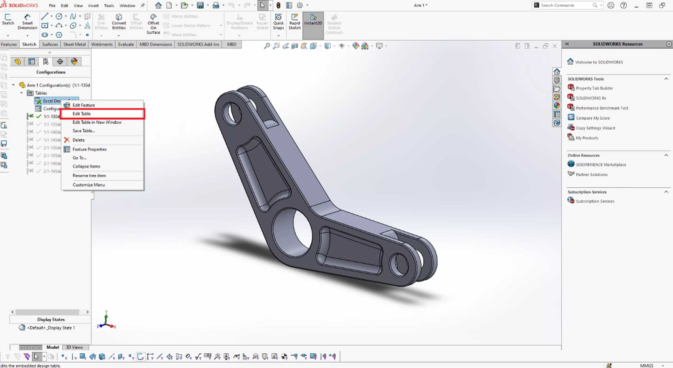
Since the table is closed, right-click on Excel Design Table in the ConfigurationManager tree and select Edit Table.
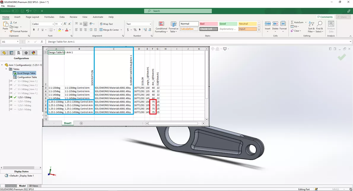
With our table open, add a column $LIBRARY:MATERIAL@ARM1. The material for each configuration will be SOLIDWORKS Materials:6061 Alloy. We'll change the configuration names for each 2:1 to 1.25:1. For the description, we will add the Ratio and Deg for each configuration.
Lastly, we will change four inputs for dist_1@Sketch1. In Column E, rows 7-10, change the distance from 120 to 75. This will match the ratio for each configuration. The data in the table should now be complete, and we can close out the design table.
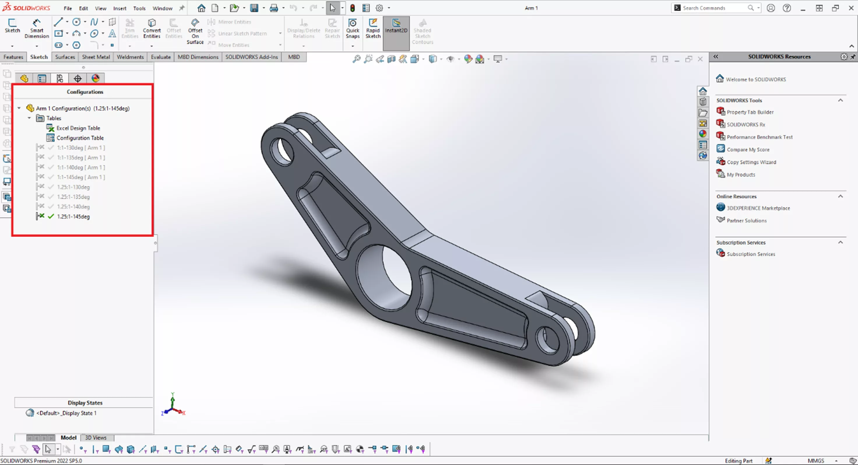
We still have our eight (8) configurations, but the new ratios of the arm and configuration names have changed. Description and material have been added also.
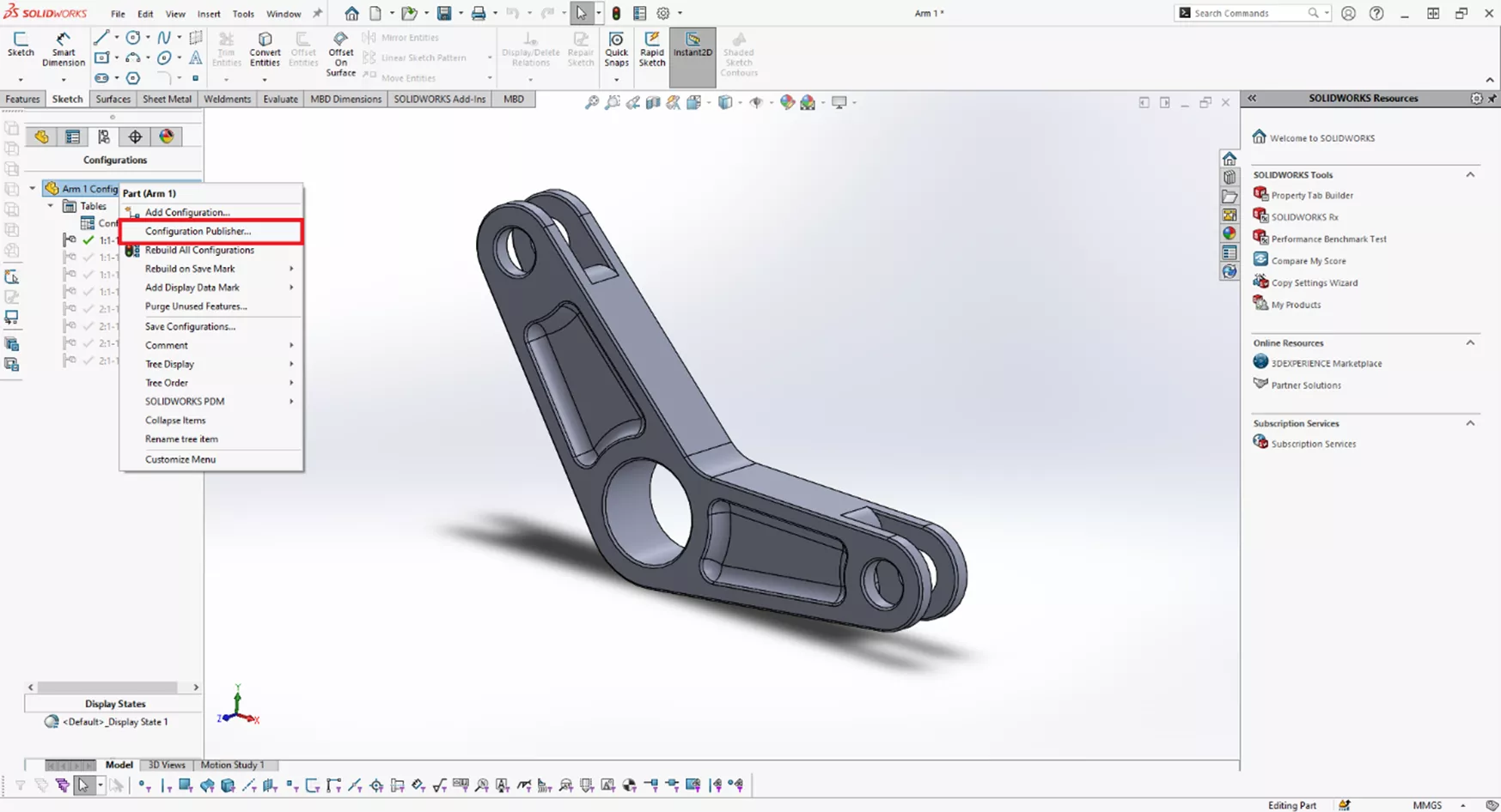
The configurations can now be published. Rght-click on the part name at the top of the ConfigurationManager and select Configuration Publisher. This will open both the design table in a separate Excel window as well as the Configuration Publisher tool.
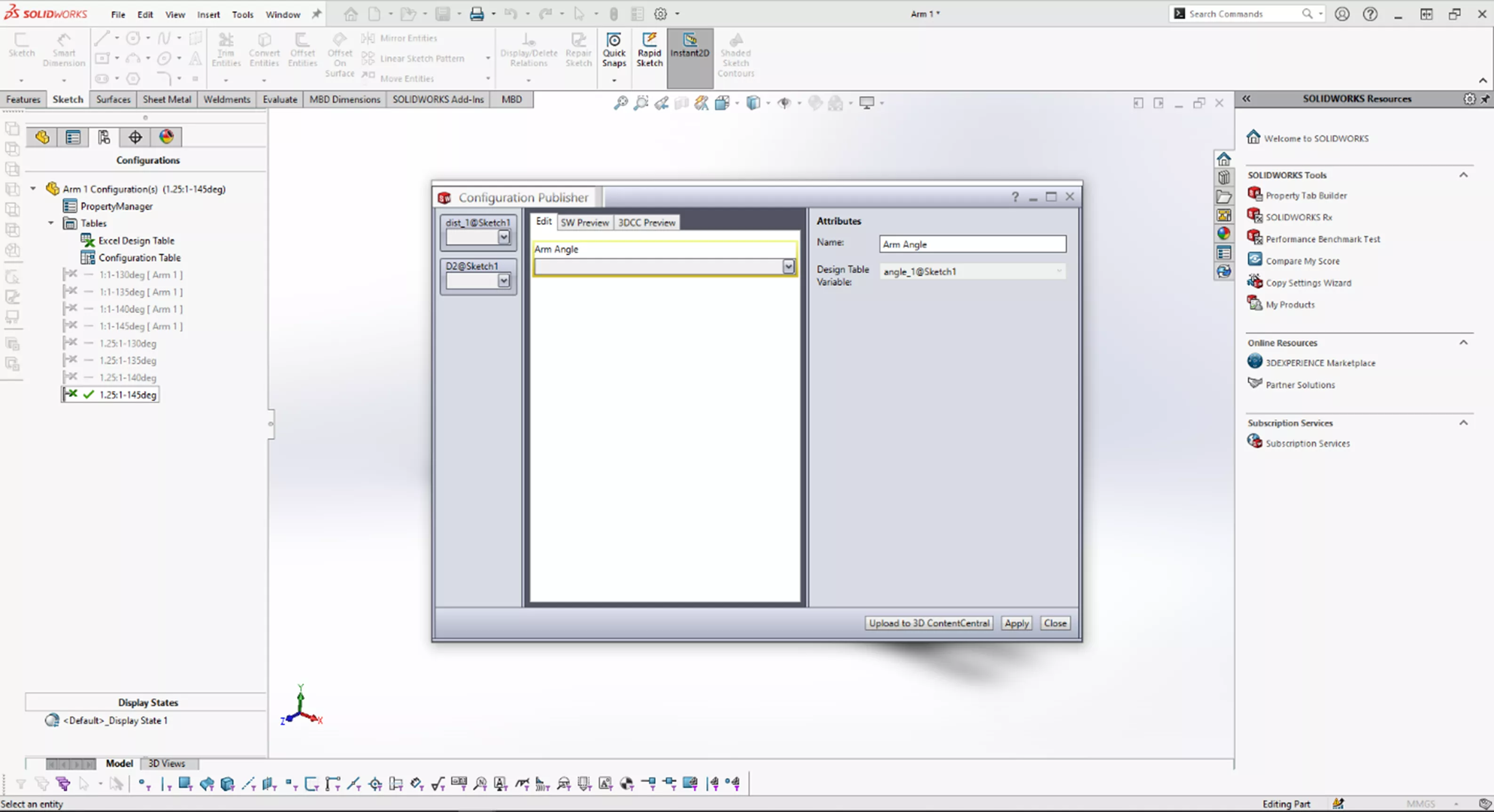
There are three tabs at the top: Edit, SW Preview, and 3DCC Preview.
The Edit tab is where we create attributes for the dropdown lists.
Notice it tells us to “Drag a control from the left pane…”. We will drag angle_1@Sketch1.
On the right side of the Configuration Publisher is its Attributes. We will change the name to Arm Angle then we will select Apply.
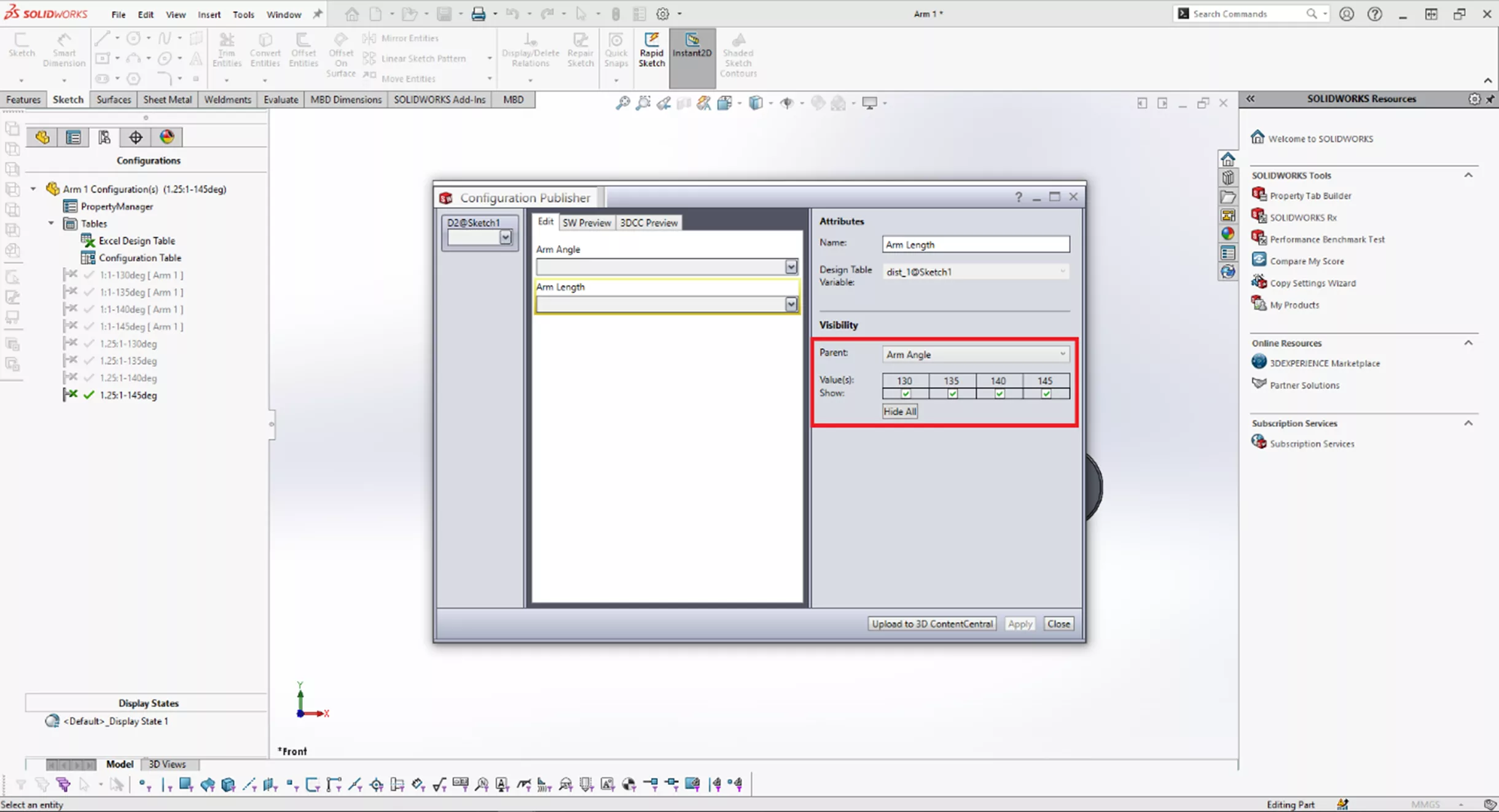
Because of how this part is designed, we only need to have two controls. We'll add dist_1@Sketch1 to the list and rename it to Arm Length. This is the same step as with Arm Angle.
For Visibility, we will choose Parent. This will automatically populate “Arm Angle”. We will leave all configurations checked for visibility and select Apply.
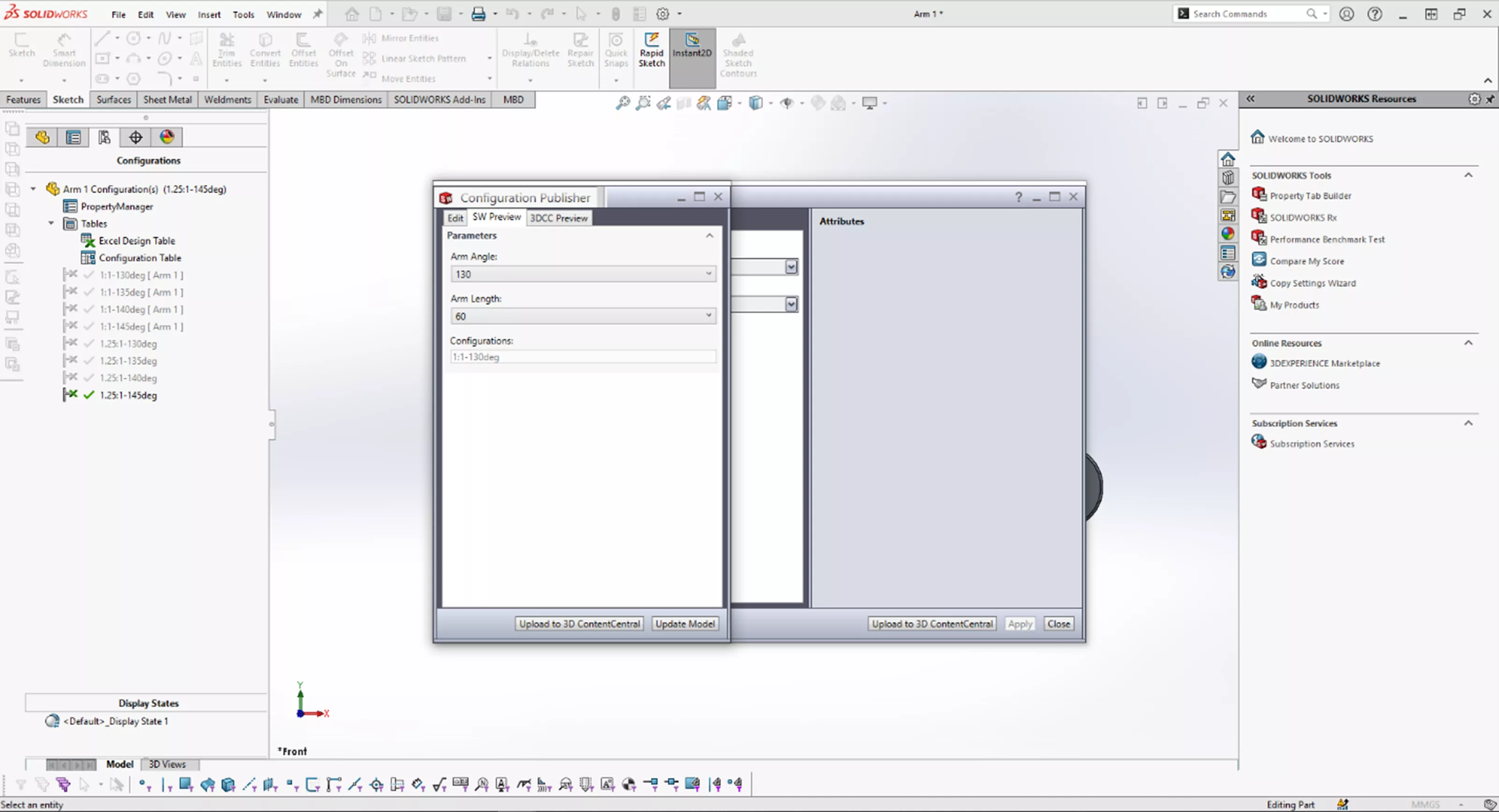
Both Preview tabs will preview what the menus will look like when components are placed in an assembly. Select the SW Preview. Set the Arm Angle and then select the Arm Length. When both of these are selected, the correct configuration is listed.
With the Configuration Attributes created, close the Configuration Publisher and save the part. Now when we place this component into an assembly, it will first ask us to select the attributes we want to apply to the component.
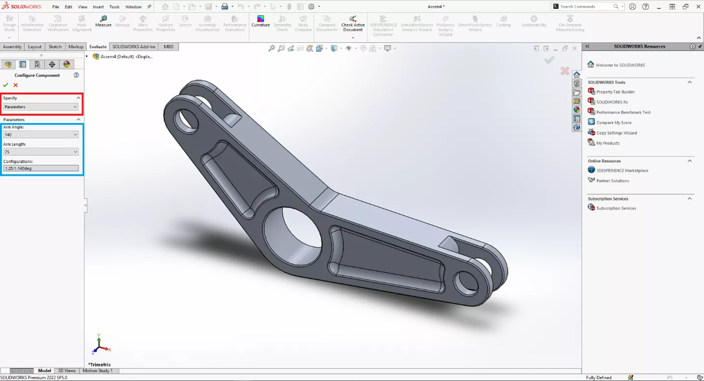
There are several options. The top option specifies whether to drive the configuration by the parameters created in Configuration Publisher or drive it by picking a specific configuration. Here, we will leave it set to Parameters and select the angle and arm length; we can choose which configuration we want to be placed into the assembly.
Conclusion
This completes our two-part guide for Configuration Publisher. To quickly review these steps, in part one, we learned how to use a Configuration Table to quickly create configurations, rename them, and then publish this to create a dropdown menu when selecting the component in an assembly.
Here, we created a design table to use configuration publisher to create custom dropdown lists. Once we insert the part into an assembly, SOLIDWORKS will require us to select these parameters to specify the configuration we want to place.
Sample Part
To see an example part, download the file created here.
I hope you found this tutorial helpful. Check out more SOLIDWORKS tips and tricks listed below.
More SOLIDWORKS Tutorials
Managing External References in SOLIDWORKS Assemblies
SOLIDWORKS Top-Down Assembly Modeling Quick Tip
SOLIDWORKS Drawing Performance: Turn Off Detailing Mode
SOLIDWORKS FilletXpert Tool Tutorial
Applying a New SOLIDWORKS Drawing Sheet Format to Existing & Future Drawings
![]()
About Kenny Bacon
Kenny Bacon is a SOLIDWORKS Technical Support Engineer at GoEngineer.
Get our wide array of technical resources delivered right to your inbox.
Unsubscribe at any time.