SOLIDWORKS Flow Simulation: Isolate Parts in a Temperature Solid Plot
Have you ever wanted to isolate part files in SOLIDWORKS Flow Simulation cut plots as you can easily do in SOLIDWORKS Simulation plots? It is possible to do this in Flow Simulation but requires a bit of a workaround. This workaround works best with the flow variables that have “Solid” after them. Like the variables Density (Solid), Domain Index (Solid), and Temperature (Solid). This article will focus on the Temperature (Solid) variable as it is the most used of the “Solid” Flow variable types. The Temperature (Solid) variable displays the temperature only in solid geometry in SOLIDWORKS Flow Simulation.
One of the most used plots in SOLIDWORKS Flow Simulation is the Cut Plot. Say a user would like to see what is happening on an electronics board as it heats up, but only cares about a few specific pieces on the electronics board and wants to make sure those parts do not go over their specified temperature ranges (see Figure 1). The components of interest on this electronics board are the Micro Processor, the Small Chip, and LED lights 1 and 3.

Figure 1: Electronics board with parts of interest pointed out
The problem with the Cut Plot option is that it is limited in its customization. The user can make a cut plot on a single plane for the whole computational domain (see Figure 2). However, if the user wants to focus on a few specific parts and nothing else then the only other option in the cut plot property manager is to use the Crop Region option (see Figure 3).
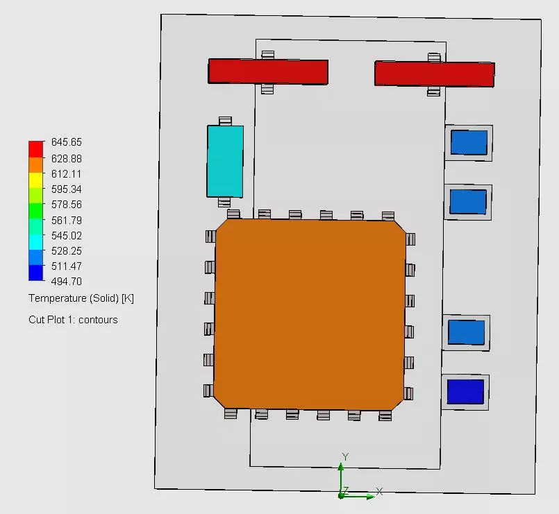
Figure 2: Temperature (Solid) Cut Plot for all solid geometry in the cut plot plane
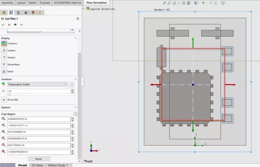
Figure 3: Cut Plot Crop Region highlighted in RED
The problem with the Crop Region option is that you can only crop one region, and it always crops in a rectangular or square shape (See Figure 4). The Crop Region option can be useful in some situations, but if the user wants to show only specific part files in the whole plot while excluding other parts, then this is not a good option.
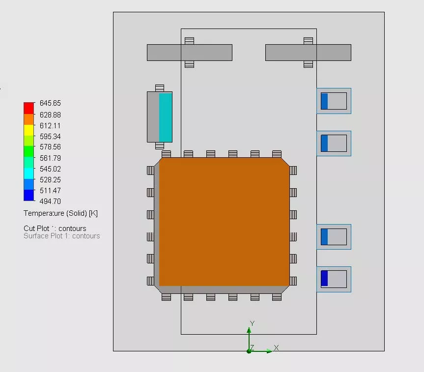
Figure 4: What the Cut Plots Crop Region tool shows of the results
To show only specific part files the user should use the Surface Plots option. Using this plot the user can quickly click on only the exposed faces to see what is happening on the outside of the part files. What if the user wants to know what is happening in the bulk of the part files? In that case, the user should still use the Surface Plots option but first, open each of the part files of interest and create a flat surface through the part file at a depth of interest.
I did precisely that with the parts of interest in this document’s example. In Figure 5 a surface created through the middle of the microprocessor is used to visually show the solid temperature of the MicroProcessor using the Surface Plots option (see Figure 5).
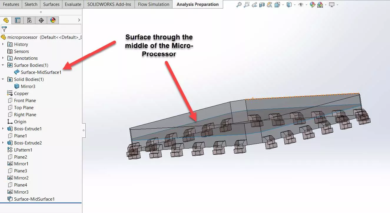
Figure 5: Created surface through the middle of the Micro-Processor part file
Back in Flow Simulation, I inserted a new Surface Plot using the Temperature (Solid) variable and selected the surfaces I created in the part files of interest. After doing so, I was able to see the temperature at these surfaces and only these surfaces as if it was a cut plot of only the specific part files that I chose (See Figure 6).
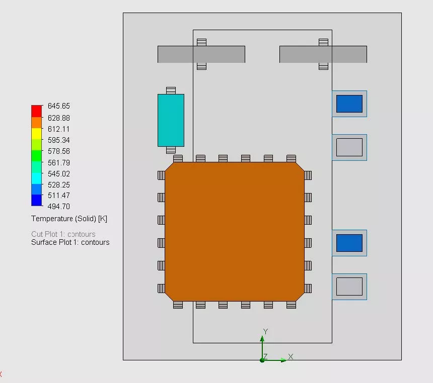
Figure 6: Temperature (Solid) surface plot of the part files of interest
More SOLIDWORKS Flow Simulation Tutorials
Understanding the Tesla Valve Using SOLIDWORKS Flow Simulation
Customizing SOLIDWORKS Flow Simulation Feature Tree Categories
Different Pressures in SOLIDWORKS Flow Simulation
Tank Sloshing Using SOLIDWORKS Flow Simulation
Backspin is Important to Your Basketball Free Throw! A SOLIDWORKS Simulation Study

About Taran Packer
Taran is a SOLIDWORKS Simulation Technical Support Specialist at GoEngineer. He has a Bachelor’s degree in Biomedical Engineering from the University of Utah. Taran enjoys learning about different tools in SOLIDWORKS Simulation, Flow Simulation, and Plastics.
Get our wide array of technical resources delivered right to your inbox.
Unsubscribe at any time.