SOLIDWORKS MBD - Understanding DimXpert Colors
SOLIDWORKS MBD tells us graphically which features of a part are fully-constrained, under-constrained, over-constrained, or don’t have any constraints. It does so by applying specific colors to the model itself as well as to the design tree. This helps check a model to see if it’s ready to be manufactured.
Showing Colors Using Tolerance Status
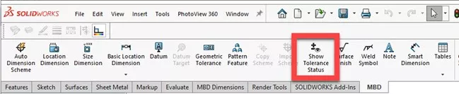
The tool that shows the DimXpert colors we are looking for is labeled Show Tolerance Status. This tool is located in the CommandManager under the MBD tab.
What the Colors Mean
Graphics Area
In the graphics area, you will see up to three new colors:
- Green means a feature is full-constrained
- Yellow means a feature is under-constrained
- Red means a feature is over-constrained
If you see the original part color (gray in this example), it means no GD&T data was applied to that feature.

FeatureManager Design Tree
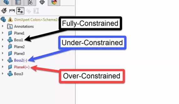
The FeatureManager Design Tree has its own color scheme:
- Black means fully-constrained
- Blue with a (-) means under-constrained
- Red with a (+) means over-constrained.
Why Does It Matter?
It’s your part, so it’s not completely necessary to fully constrain everything. This is not the same a fully defining a part when modelling it. What matters is that enough information is contained in the 3D view for the part to be manufactured.
Changing the Colors
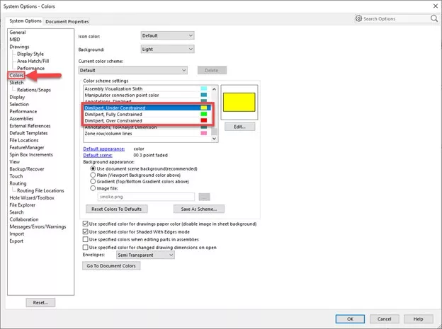
Don’t like the colors? No problem. The default colors in the graphics area can be changed at any time. The setting to do so is under Tools > Options > System Options > Colors. Scroll down under Color Scheme Settings until you see the DimXpert colors to change them.
I hope you found this tutorial helpful. For more tips and tricks to get the most out of your SOLIDWORKS, check out the related articles listed below.
More SOLIDWORKS Tutorials
SOLIDWORKS MBD Custom 3D PDF Template Tutorial
Easy Way to Hide/Show SOLIDWORKS Dimensions at Part Level
Understanding Colors In SOLIDWORKS
How to Color Sketches in SOLIDWORKS

About Gary Ballentine
Gary Ballentine is a Mechanical Engineer based out of our Headquarters in Salt Lake City, Utah. He earned a Bachelor’s degree from the University of California, Davis, a certification in Technical Writing from San Francisco State University, and a Bachelor’s degree in Mechanical Engineering from the University of Utah. Gary has been part of the GoEngineer family since April 2019 as a Support Engineer and Certified SOLIDWORKS Instructor.
Get our wide array of technical resources delivered right to your inbox.
Unsubscribe at any time.