Thickness Analysis Tool - SOLIDWORKS Utilities
The Thickness Analysis tool in SOLIDWORKS is used to find areas of your model that are either thicker or thinner than a specified target thickness value. While this is a helpful feature for many different situations, it is especially crucial for cast and molded plastic injection parts, where uniform wall thickness promotes even filling and cooling. You can find the Thickness Analysis tool in the Evaluate tab of your Command Manager or in the Tools dropdown at the top right.
Thickness Analysis is part of the SOLIDWORKS Utilities add-in, which contains a suite of tools used to evaluate solid geometry. Thickness Analysis is only available in parts and requires a license of SOLIDWORKS Professional or Premium to use.
Setting up an analysis – What’s in the PropertyManager?
There are three sections in the Thickness Analysis PropertyManager:
- Analysis Parameters
- Color Settings
- Performance/Accuracy
Analysis Parameters
Analysis Parameters is where you set up the Thickness Analysis calculation. You can choose to either find regions that are thicker or thinner than your target thickness. If you select the radio button for Show thin regions, you'll enter a Target thickness and the Thickness Analysis will calculate where the model is thinner than that specified value.
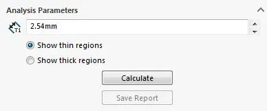
Figure 1: Analysis Parameters with Show thin regions selected
If you select Show thick regions, two additional options will appear. A Thickness Analysis showing thick regions will find areas of the model thicker than the specified Target thickness. There is an additional parameter for Thick region limit. Any area with a thickness greater than this limit will be displayed in the selected Target thickness color (see Color Settings).
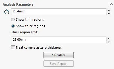
Figure 2: Analysis Parameters with Show thick regions selected
If Show thick regions is selected, there is also a checkbox for 'Treat corners as zero thickness'. With this checked, sharp corners in your model are seen by the Thickness Analysis as having a thickness of zero. The areas around these sharp corners will go to zero as they approach the corners.
Color Settings
The Color Settings section determines how your results will be displayed. If Full color range is checked, the model is displayed in the various colors of the Thickness scale. Regions equal to or thicker than your Target thickness (Show thin regions) or regions outside the thickness range (Show thick regions), will be your Target thickness color. This color can be changed with the Edit Color... button.
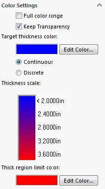
Figure 3: Color Settings section with Full color range unchecked
If Full color range is not checked, the Thickness scale becomes a gradient between your Target thickness color and Thick region limit or Minimum thickness color. The part will be shown in this gradient.
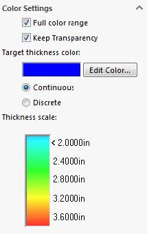
Figure 4: Color Settings section with Full color
The radio buttons for Continuous and Discrete determine whether the Thickness scale's display will be a smooth gradient between colors or if distinct bands of color will be used instead.
Performance/Accuracy
The Performance/Accuracy section settings are mostly optional. Thickness Analyses can only be performed on one body at a time so, if you are working with a multibody part, you will need to select which body you want to study under Body for analysis. The body can be selected from the graphics area or the Solid bodies folder in your Feature Tree.
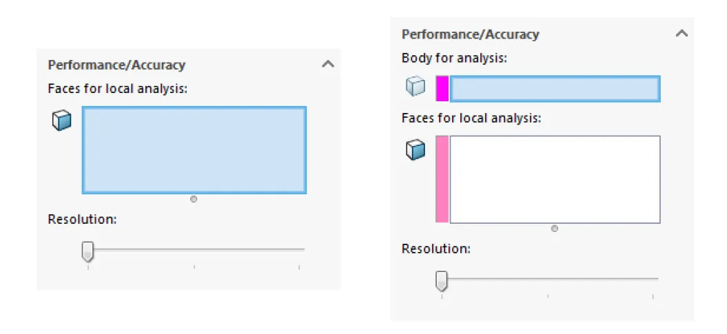
Figure 5: Performance/Accuracty section with a single bodied part (Left) versus a multibodied part (Right)
If you are only interested in the thickness of certain areas of your model, you can speed up your Thickness Analysis by selecting the associated faces under Faces for local analysis.
You can further improve the performance of the analysis by moving the Resolution slider to the left. A higher resolution (slider to the right) corresponds with greater color precision in your results.
Once you've set up your Thickness Analysis, to run it, return to the Analysis Parameters section and press the button for Calculate. You can see the thickness values in different regions of your model by mousing over it in your graphics area - text displaying the thickness value will appear next to your cursor.
Also in the Analysis Parameters section is a Save Report button. This will generate a report that includes a list of the options you used for the Thickness Analysis, four ranges of critical thicknesses and how many faces, the amount of surface area, and the percentage of analyzed area that fall into those ranges, and all Critical features (i.e., features that do not meet the Target thickness). These critical features are listed in order of the maximum deviation from the Target thickness of the feature. This report also includes Mass Properties of the model, specifically, it's surface area, volume, mass, and any Model Views you chose to export.
The Save Report option will create a folder in a location of your choice that includes this report, in .htm format, and associated files. Below are the options available when saving a report.
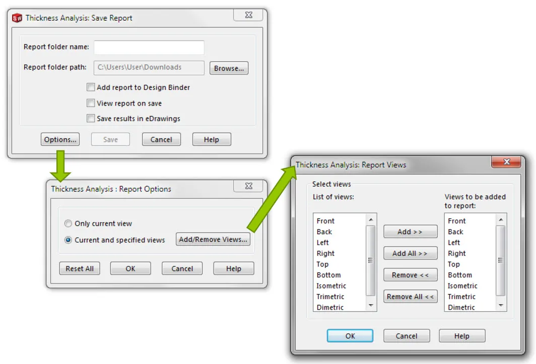
Figure 6: Save Report options
Expand Your SOLIDWORKS Utilities Skillset
Report Manager - SOLIDWORKS Utilities
Find and Replace Annotation - SOLIDWORKS Utilities
The Power of Power Select- SOLIDWORKS Utilities

About Lauren McGarry
Lauren McGarry is a Certified SOLIDWORKS Expert based out of San Diego, California. She earned her Bachelor of Science degree from Case Western Reserve University and has been with GoEngineer as a Technical Support Engineer since 2016.
Get our wide array of technical resources delivered right to your inbox.
Unsubscribe at any time.