Weld Bead vs Fillet Bead: SOLIDWORKS Feature Comparison
You might ask yourself why there are two Bead features in SOLIDWORKS Weldments; Weld Bead and Fillet Bead. In this quick tip, we compare the two to help you better decide when to use one over the other.
SOLIDWORKS Weld Bead Feature
In a previous article, we discussed adding a Weld Bead Feature to your SOLIDWORKS Weldment Part file. Refer to the following article to learn how to add Weld Beads to your Weldment Part file: Creating and Adding Weld Beads in SOLIDWORKS Models & Drawings.
Benefits of the Weld Bead
In SOLIDWORKS, the Weld Bead’s major advantage over the Fillet Bead is performance. The Weld Bead feature defines your welds but does not generate any solid bodies. The Weld Bead is a graphical body (think “Cosmetic Threads” for Weldments) that won’t require extra resources from your PC, allowing for a smoother modeling experience.
- Suggested Article >> Optimizing SOLIDWORKS for Faster Performance
Although the Weld Bead Feature creates a graphical body, a Weld Bead Folder is populated in your FeatureManager Design Tree. Weld Bead Properties contain such details as Weld Material, Weld Process, Weld Length, etc. (Figure 1) and can be shown in your SOLIDWORKS Drawing in a Weld Table (Figure 2).
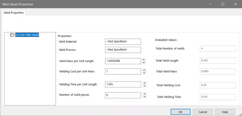
Figure1: Weld Bead Properties
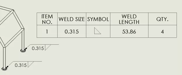
Figure 2: Weld Bead Properties displayed in a Drawing using a Weld Table
SOLIDWORKS Fillet Bead Feature
The Fillet Bead feature does not generate Custom Properties that could be located in a weld table. The Fillet Bead Feature generates a solid body found in your SOLIDWORKS Weldment Multibody part file. (Figures 3 & 4)
By using the Fillet Bead option to define your welds, the SOLIDWORKS Weldment file can now be accurately used to run Interference Detection in a tight corner to verify whether your weld bead might cause issues later in your Assembly if another component is mounted in close proximity to the weld.

Figure 3: Fillet Bead feature: Note that the feature is in the FeatureManager Design Tree and not the Weld Folder. Measurements between the edge of the bead and the mounting holes can be used to prevent interferences in final assembly
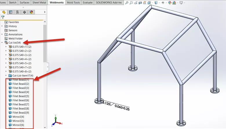
Figure 4: Fillet Bead features appear in the Weldment Cut List. Note that Fillet Beads can be patterned (Mirrored in this example)
How to Add a Fillet Bead in SOLIDWORKS
To add a Fillet Bead to your Weldment, go to Insert > Weldments > Fillet Bead. (Figure 5)
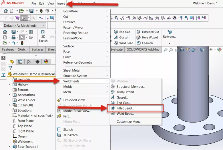
Figure 5: Where to find the Fillet Bead tool
With the Fillet Bead feature open, select the type of weld from the drop-down (Full Length, Intermittent, or Staggered). (Figure 6)
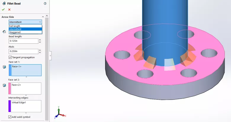
Figure 6: Fillet Bead options for weld type, bead length, pitch, and optional Weld Symbol
Select the faces of the two bodies to be welded and set the fillet size and/or pitch options. (Figure 7)
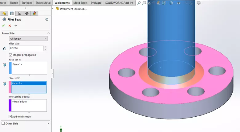
Figure 7: Fillet Bead Feature with Full Length, 0.125” Fillet Size, and Weld Symbol selected
Since the Fillet Bead feature generates a solid body, it will aid in calculating accurate Mass Property results.
Additionally, because the Fillet Bead generates a physical representation in your SOLIDWORKS Part file, drawing views will automatically include the Fillet Bead. (Figures 8 &9)
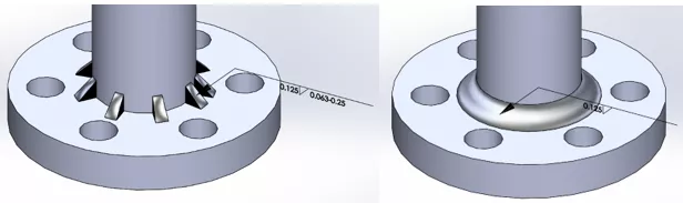
Figure 8: Examples of Finished Fillet Bead features in both Intermittent (left) and Full Length (right)
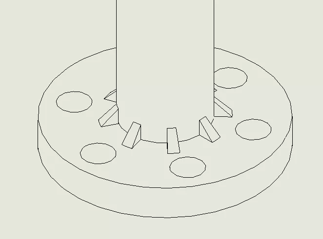
Figure 9: Graphical representation of an Intermittent Fillet Weld Bead in a Drawing
Conclusion
The choice is yours to make. As with any tool in SOLIDWORKS, the decision on which feature to use is up to the end user. The choice comes down to how you intend to use the weld information.
If you’re creating a detailed Weldment Drawing, including weld properties and callouts, the Weld Bead feature would be preferred while minimizing the impact on performance.
However, if the physical weld bead is required for inspection or mass property calculation, the Fillet Bead is the feature to select.
I hope you found this quick tip helpful. Learn more about SOLIDWORKS by checking out additional tutorials below.
Want to become an expert?
Take the official SOLIDWORKS Weldments training course from GoEngineer.

More SOLIDWORKS Tutorials
SOLIDWORKS Design Checker Tool Explained
Why is My Assembly Invisible in SOLIDWORKS?
SOLIDWORKS Tutorial: Master Modeling Techniques
SOLIDWORKS Drawing Referencing Old Files

About Brad Hakeman
Bradley Hakeman is an Application Engineer at GoEngineer. When he isn’t helping customers with their SOLIDWORKS related challenges, he is keeping up on the latest features of SOLIDWORKS. In his spare time, he’s trying to sort out his kids’ soccer schedules and working on household projects, many of which were designed in SOLIDWORKS. Most recently, he has taken up woodturning, currently focusing on pen making.
Get our wide array of technical resources delivered right to your inbox.
Unsubscribe at any time.