Create Zero Radius Fillet Using SOLIDWORKS Split Line
SOLIDWORKS allows users to create multi-radius fillets that terminate with a zero radius, smoothly transitioning into the model’s edge. However, a vertex needs to be selected to create a zero radius fillet, and sometimes a model doesn’t have a vertex where we want the radius to reach zero. Here is where an a-typical use of the Split Line comes into play.
Using a Multi-Radius Fillet
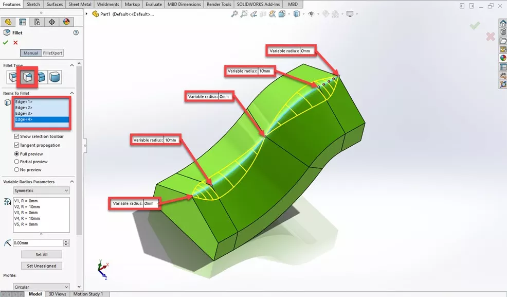
In SOLIDWORKS, a multi-radius fillet allows for a smooth transition from a standard fillet back into the model’s original geometry. Multi-radius fillet is the second Fillet Type in the Fillet PropertyManager, and we can select the edges to fillet in the graphics area like we would for a regular constant radius fillet. We can then specify the radius for each point along the edge.
In this model, there are three points where a zero radius fillet is possible: both ends and the section near the middle where a tangent relationship exists between the two arcs.
But what if we want to locate the zero radius somewhere else along the model’s edge? If we try to select any other location, it doesn’t work. Enter the Split Line!
Using a Split Line to Create a Vertex
The SOLIDWORKS Split Line tool is intended to split a part into two pieces so that a mold can be created. But it doesn’t have to be used that way.
First, create a sketch line over the model where the zero radius fillet is needed.
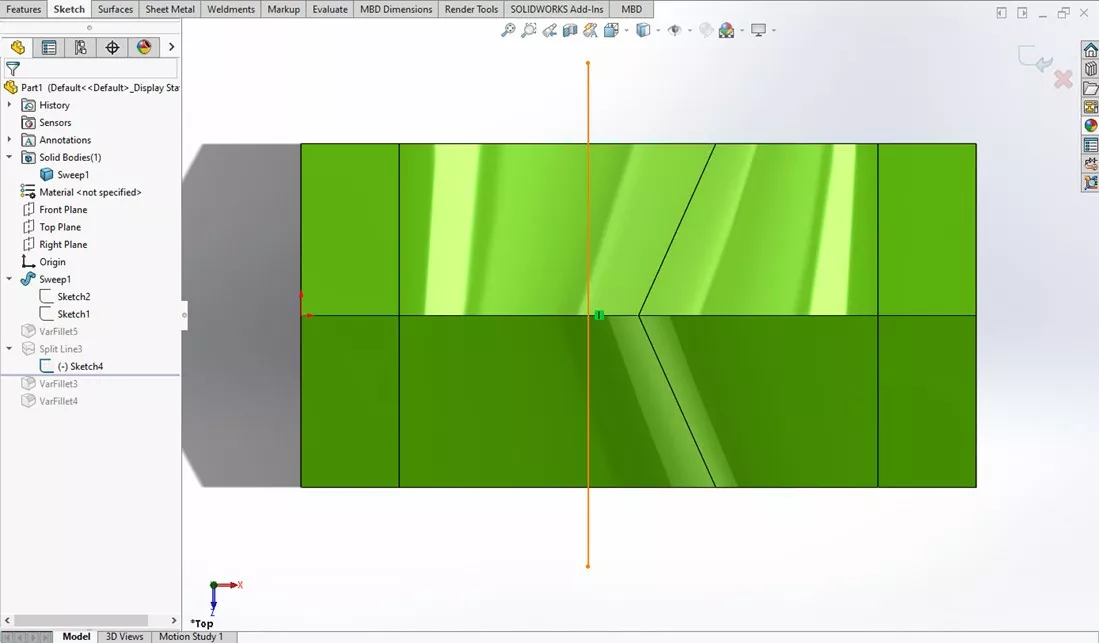
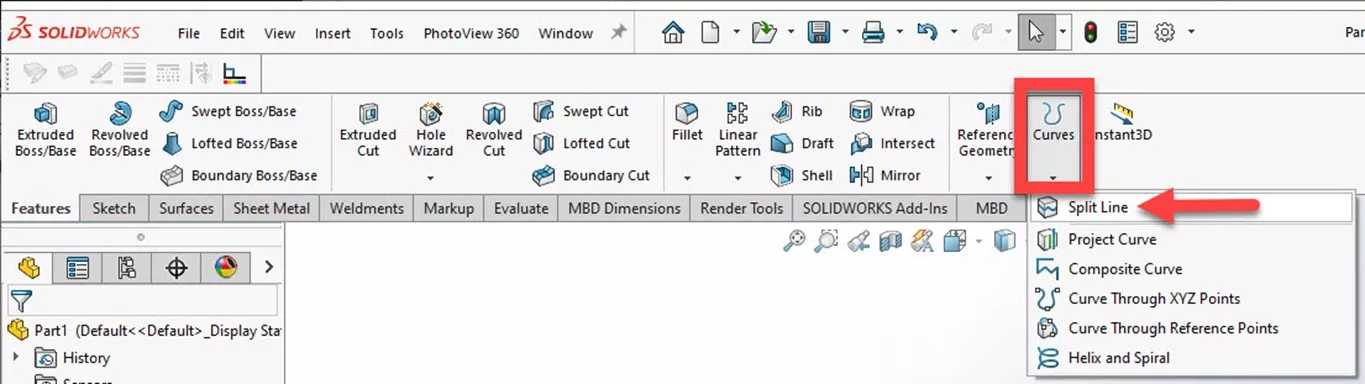
Next, select the Split Line tool on the right side of the Features tab in the CommandManager. Select the newly created sketch to create the Split Line.
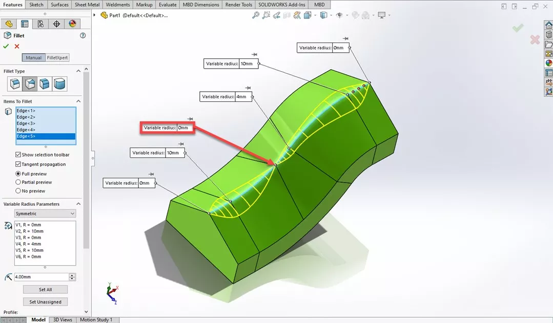
We now have a vertex where the split line intersects the edge, and we can set the radius to zero here.
Want to Become An Expert?
Take the official SOLIDWORKS Advanced Part Modeling self-paced training course to learn more about working with these features, commands, and design tools.
Want to learn more about SOLIDWORKS? Check out more tips and tricks below.
More SOLIDWORKS Tutorials
SOLIDWORKS Mold Tools: Split Line & Parting Line Explained
SOLIDWORKS Partial Chamfers & Fillets Explained
Weld Bead vs Fillet Bead: SOLIDWORKS Feature Comparison
Creating a Multi-Sheet Drawing Template in SOLIDWORKS

About Gary Ballentine
Gary Ballentine is a Mechanical Engineer based out of our Headquarters in Salt Lake City, Utah. He earned a Bachelor’s degree from the University of California, Davis, a certification in Technical Writing from San Francisco State University, and a Bachelor’s degree in Mechanical Engineering from the University of Utah. Gary has been part of the GoEngineer family since April 2019 as a Support Engineer and Certified SOLIDWORKS Instructor.
Get our wide array of technical resources delivered right to your inbox.
Unsubscribe at any time.