Math and Art of Smooth-Rollers in SOLIDWORKS
Patrick Roberts, geometry enthusiast and technician at a large tech company, was presented with a geometry puzzle of creating the ultimate smooth-rolling solid. With his brainpower and some spare time spread out over a couple of weeks, he came up with one of the simplest, non-spherical smooth-rolling solids. His article, here, outlines the final product and a rough proof of its mathematical soundness. In July of 2021, his creation was verified by the work of three mathematicians from UNAM.
In this article, we will show the properties of the Roberts Tetrahedron using SOLIDWORKS so you can build your own from scratch. If you’d like to skip the challenge, we've provided a version at the end of the article that you can download and print to have on your desk or show to your friends and family.
Solids of Constant Width
To create a solid (other than a sphere) that rolls smoothly between planes, you need to create a shape that has constant width.
This means that when the solid is placed between two parallel planes, it always maintains the same distance between the planes no matter the orientation. One example of a 2-dimensional solid, which has this property, is called a Reuleaux Triangle.
The Reuleaux triangle has a variety of uses. One common application is in the Wankel engine. (Figure 1)
Figure 1 - Wankel Engine animation (source: http://animatedengines.com/wankel.html)
Or it’s used by some enthusiasts to help drill square holes shown in the animation below.
Figure 2 - Square hole drill (source: https://youtu.be/L5AzbDJ7KYI )
Reuleaux Tetrahedron
To build our own Roberts Tetrahedron, we can start by constructing a shape that is close to constant width: the Reuleaux Tetrahedron. (Figure 3)
Figure 3 - Reuleaux Tetrahedron shown in the middle
Building this tetrahedron is simple since it involves combining four symmetrically center-spaced spheres. (Figure 4)
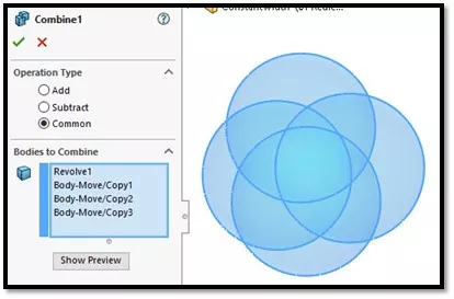
Figure 4 - Combine common
Peapod Round
After building the Reuleaux Tetrahedron, the next step is to round all corners, but in a particular way. (Figure 5)
Figure 5 - Peapod rounded corners
As described by the mathematicians at UNAM, this round must take the shape of a peapod where each “pea” (sphere) is tangent to both the adjoining surfaces and to the edge of the flat tetrahedron that is embedded inside the Reuleaux Tetrahedron. (Figure 6)
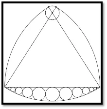
Figure 6 - Peapod round section view
We've zoomed in on the completed peapod round so you can see more clearly what it will look like once we complete the next steps. (Figure 7)
Figure 7 - Peapod round animation
Peapod Round Construction
SOLIDWORKS does not have a feature that will sweep a variable radius sphere. Instead, to build the surface for the peapod round, we can use the Surface Sweep command with a circle. An equation-driven path will be at the center of the sweep and a guide curve will reduce the radius to zero as it approaches the ends of the path. (Figure 8)
Figure 8 - Surface sweep construction of peapod round
We built the path first using an equation-driven curve. (Figure 9) This is a curve that describes the location of the center of the spheres. The equation for this is given in Roberts' original article.
Figure 9 - Center path of spheres given by Roberts
We will then draw a circular profile that will follow the path and will stay normal to it.
Will using a circle instead of a sphere work?
Figure 7 (above) should provide a “designer’s proof” that the result should at least be extremely close (likely within 3D printing tolerances) if not an exact match.
A guide curve is needed to drive the radius of this circle along its path. This guide is provided by the straight edge of the embedded tetrahedron. (Figure 10)
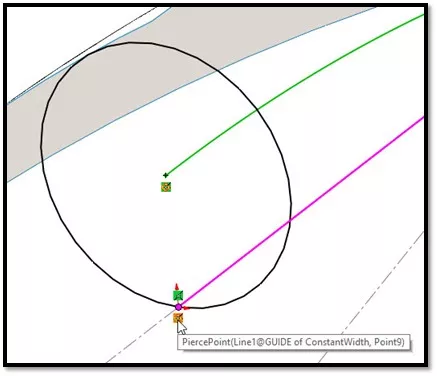
Figure 10 - Profile for a sweep
Finally, the circular profile orientation needs to follow the path instead of remaining in a constant orientation to best mimic what a spherical sweep would do. (Figure 11)
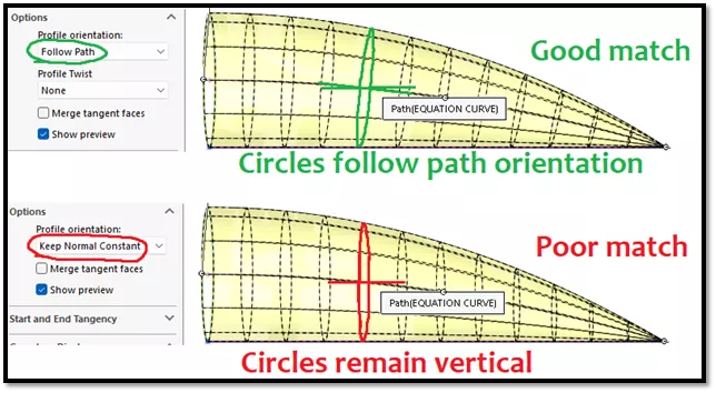
Figure 11 - Circular profile orientation needs to follow the path for an accurate result
Surprisingly, the sweep completed without errors even as the circle‘s radius reduced to zero at the vertex of the tetrahedron.
With the difficult part out of the way, all that’s left is to copy, mirror, pattern, trim, and knit these same surfaces to create the final Roberts Tetrahedron.
Reuleaux tetrahedron vs Roberts tetrahedron
How well does the Roberts Tetrahedron perform compared to its non-constant width cousin, the Reuleaux Tetrahedron? We can set up a virtual test using SOLIDWORKS Motion and the difference is clear.
Figure 12 - SOLIDWORKS Motion study on Reuleaux (top) versus Roberts (bottom)
The Realeaux tetrahedron was a bumpy ride compared to the smooth ride of the Roberts tetrahedron.
Finally, we tested a 3D printed version.
Figure 13 - 3D printed Roberts Tetrahedron
If I hadn’t already known what was under the book, I would have thought it was on ball bearings. But don’t take our word for it, try printing your own! Download available here.
A version of the Roberts Tetrahedron converted into 4-sided dice was also featured on the Grand Illusions YouTube channel. Check out their video here!
Summary
Constructing this simple-looking shape involved some tricky SOLIDWORKS features and creative ideas to challenge even advanced users.
- Combine common
- Equation-driven spline
- Sweep with a guide curve
- Surface patterns, trims, and knitting
Finally, we simulated the difference in behavior between the two designs using SOLIDWORKS Motion to verify the performance of our improved design.
Related Articles
Understanding the Tesla Valve Using SOLIDWORKS Flow Simulation
Backspin is Important to Your Basketball Free Throw! A SOLIDWORKS Simulation Study
Understanding the Rattleback Mystery with SOLIDWORKS Motion
SOLIDWORKS Motion: A Tip for Handling Performance "Hogs"
What's New SOLIDWORKS 2022: Routing, Structure Systems, Parts & Features

About Shaun Bentley
Shaun Bentley is passionate about applied mathematics and engineering, which led him to pursue and understand real world applications of FEA, CFD, kinematics, dynamics, and 3D & 2D modeling. He teaches many simulation classes to both new and advanced users attending training at GoEngineer. Since 2006, Shaun has been working with simulation tools to solve real world engineering problems. With every new project, he seeks to find ways to push simulation to its uppermost limits, even going so far as to write bespoke code and macros. He has passed the Michigan FE exam and mentors or consults for virtually any industry that uses SOLIDWORKS, especially automotive and automated tools. He is a speed 3D modeling champion and one of the first Certified SOLIDWORKS Experts in Simulation in the world.
Get our wide array of technical resources delivered right to your inbox.
Unsubscribe at any time.