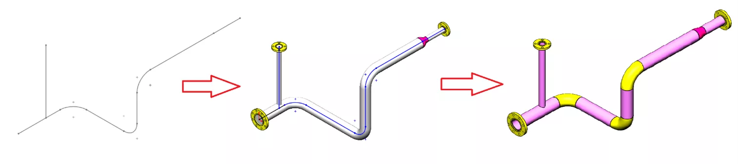
SOLIDWORKS Pipe Route Overview
SOLIDWORKS Routing helps automate four different types of routes, including piping, electrical, Tubing, and HVAC. Routing is included in SOLIDWORKS Premium and can be purchased as a separate add-in for Professional or Standard licenses. Piping helps create the pipes between components without having to manually create sweeps or extrudes.
This article provides an overview of SOLIDWORKS Pipe Route and is a quick start for getting started. If you'd like to dive into SOLIDWORKS Routing a little deeper, visit the article SOLIDWORKS Routing 101: Pipe Design.
SOLIDWORKS Routing Add-In Location
Navigate to Tools > Add-Ins and enable the check box for SOLIDWORKS Routing in the left column to open in the current session of SOLIDWORKS.
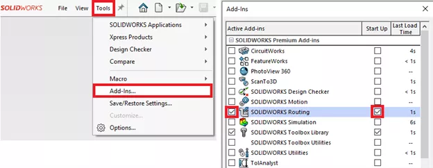
The Add-Ins option can also be selected from the Options gear drop-down arrow.
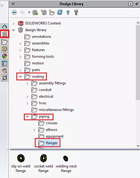
In the Task Pane, on the right-hand side of the SOLIDWORKS screen, the Design Library is available which includes multiple folders. There is a piping folder with elbows, flanges, tees, etc… With a saved assembly open, you can start a new route by dragging and dropping a flange from the flanges folder.
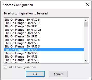
Once you drop in the flange, select a configuration for the flange size, multiple wall thicknesses, and outer diameters will be available for the three standard flanges shown below.
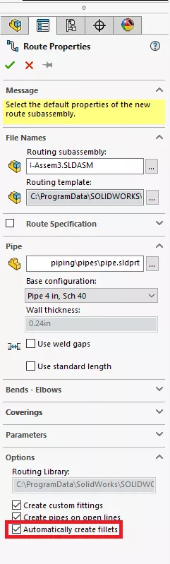
Once the flange has been placed, select any options you want to change in the Route Properties dialog box.
Once the Route Properties dialog box closes, you are now editing a 3D sketch. There will be a sketch line coming off the flange. This line represents the first stub of the route (spool).
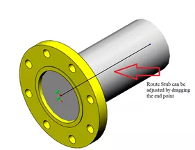
The sketch is a very special 3D sketch in that components can be added and removed along with the normal geometry creation you are used to doing in a 2D sketch.
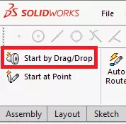
If you drag and drop a flange into an assembly and do not see the Routing Properties dialog box then make sure that the Routing add-in is turned on. You can also select Start by Drag/Drop in the upper left-hand corner of the Piping CommandManager Tab and drag in one of the flanges.
You can create lines in all three directions in a 3D Sketch. Select the Tab key while drawing a line to change the sketch plane from XY to YZ to ZX shown in the image below.
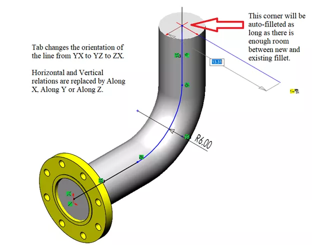
An automatic setting that should be turned on is auto-filleting of corners where two lines meet highlighted in the above route property image.
Pay attention to the radius value because you might have to manually create a sketch fillet when editing your geometry. Pipe segments and elbows will be automatically added once you exit the 3D sketch.
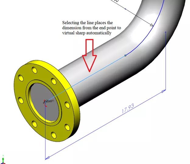
You can add dimensions to the 3D Sketch by selecting Smart Dimension and a line. The measurement will be off of the virtual sharp as shown above.
Additional Route Components
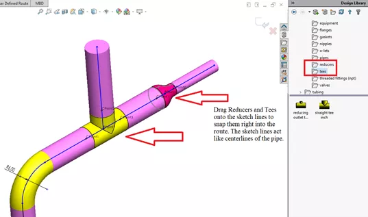
A Reducer and a Tee are added to the route shown below by simply dragging them one at a time from the Design Library onto a sketch line which acts like a centerline to the pipe.
Pipe Penetration
An additional line can be added along the route perpendicular to the route to form a tee if that is needed in the design.
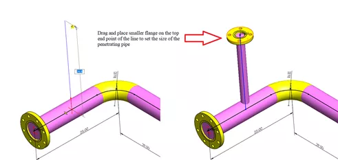
Add a flange with a different pipe diameter to the end of the line perpendicular to the route to create a pipe penetration(shown above).
Right mouse button select the intersection point and pick Penetrate.
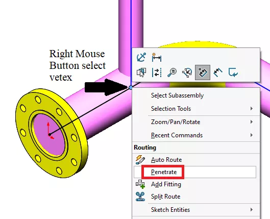
The thickness of penetration is determined by the flange size at the end of the penetrating line.
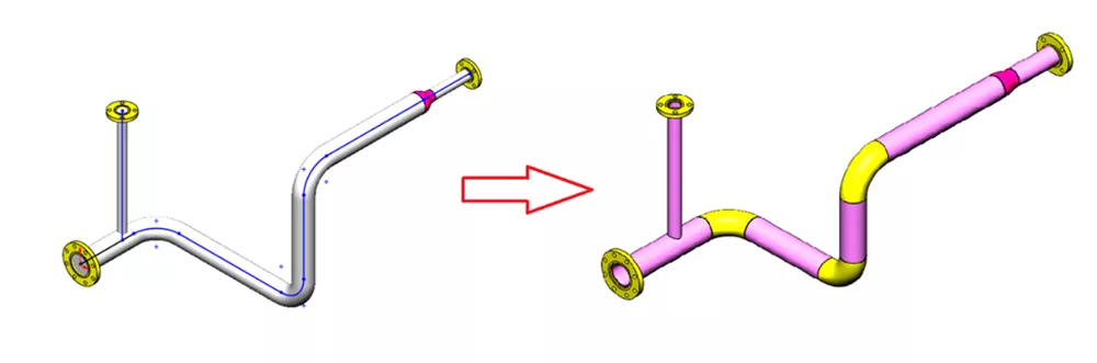
Once you are done creating the skeleton frame (centerlines) of the pipe route, you can save the sketch and exit the route. Upon exiting the route or spool sketch you will see the pipe segments added along with elbow and tees.
The route is a subassembly in the top-level assembly with folders for its own components and pipe segments. Note that after exiting the sketch you are still editing the subassembly (Edit Subassembly Mode similar to Edit Part Mode). To get back to the Top Level assembly, select Edit Component.
Editing an Existing Route
To change an existing route, including geometry changes and component addition and removal, select any part of the route and then select Edit Route. This will return you to the 3D sketch.
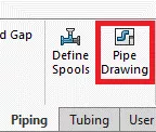
Once you are done creating the route you can quickly create a drawing using the Pipe Drawing command to quickly annotate the spools to speed up the design process.
Customization of different route components includes adding configurations to existing files located in the Design Library. Native SOLIDWORKS Parts and imported models can be turned into routing parts using the Routing Component Wizard.
Conclusion
Between drag and drop and 3D sketching, a piping route or spool can be quickly created using the SOLIDWORKS Routing Add-In. A 3D pipe route with tees and elbows can be quickly created without having to manually make geometry with 2D or 3D sweeps or extrudes. Pipe routes can be quickly modified, and drawing creation is automated using Pipe Routing functionality.
Want to become an expert?
Take the official SOLIDWORKS Routing: Piping and tubing course from GoEngineer.
More SOLIDWORKS Tutorials
What's New SOLIDWORKS 2022: Routing, Structure Systems, Parts & Features
SOLIDWORKS Routing 101: Pipe Design
SOLIDWORKS Mold Tools - Shut Off Surfaces, Parting Surfaces, and Tooling Split
Inserting Logos Into SOLIDWORKS Parts and Drawings

About Maurice Cherian
Maurice Cherian is Technical Support Engineer at GoEngineer. He was introduced to CAD while working for the Navy. Maurice has over seventeen years of Software Training and overall CAD experience. He has been using SOLIDWORKS since 2008 and is a certified expert and instructor. He provides SOLIDWORKS training and Tech Support. Maurice is active in the SOLIDWORKS User Group Community in San Diego, presenting and hosting multiple times over the last eleven years.
Get our wide array of technical resources delivered right to your inbox.
Unsubscribe at any time.