SOLIDWORKS Sheet Metal Gusset Tool Tutorial
A sheet metal gusset is an indented feature that forms a gusset to stiffen a bend in sheet metal part. Rather than using a custom-made forming tool, SOLIDWORKS includes a Sheet Metal Gusset tool. In this tutorial, we'll take a look at how to create a gusset in a sheet metal part using the Sheet Metal Gusset tool.
How To Create A Sheet Metal Gusset
- Open or create a sheet metal part with at least one bend
- Select the Sheet Metal Gusset tool from the Sheet Metal Toolbar
- Select the two faces on each side of a bend
- Set gusset parameters in the Sheet Metal Gusset dialog
- Hit the green check mark to create the specified gusset
In the following example, we will be looking at adding a 1 in gusset to a 2 in angled part.
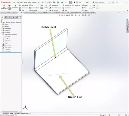
A sketch was created on the face of one of the bends to show how the gusset can be positioned.
The sketch consists of a point that we want the gusset to pass through and a line representing the angle that we want the gusset to follow.
By default, the angle will be perpendicular to the bend axis.
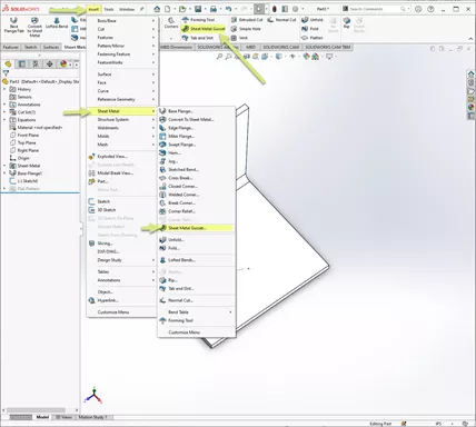
Select the Sheet Metal Gusset tool from the Sheet Metal Toolbar. Alternatively, this tool is located by going to Insert > Sheet Metal > Sheet Metal Gusset…
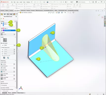
Select the two faces across the bend, then select the point field in the Sheet Metal Gusset dialog and pick the sketch point to position the gusset.
Set the Indent depth to your desired dimension (in this example 1.000”), and the gusset is created.
At this point, you could accept the defaults, hit the green check and be done.
Note: Currently, the gusset is perpendicular to the bend axis.
In the next step we will change the orientation of the gusset.
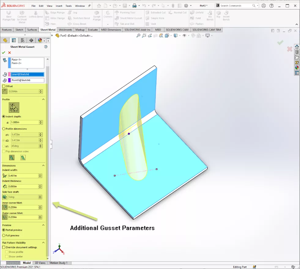
By default, the angle of the gusset is perpendicular to the bend axis. Additionally, the angle can be set according to an edge or sketch reference. To do this, select the Edge field in the Sheet Metal Gusset dialog, then select the sketch line (or reference edge).
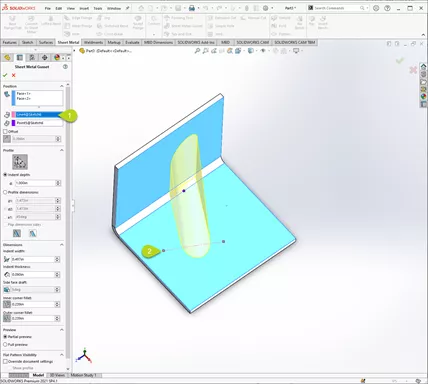
Beyond setting the size, position, and angle of a gusset, additional parameters can be controlled including profile dimensions, indent width, indent thickness, draft, corner fillets, etc.
Have more questions about SOLIDWORKS? Check out our NEW GoEngineer Community forum.
SOLIDWORKS Sheet Metal Training
Want to become an expert? Learn to build stand-alone sheet metal parts and covert conventional parts in our Professional SOLIDWORKS Sheet Metal training course.
More SOLIDWORKS Sheet Metal Tutorials
Using Sheet Metal Bodies in SOLIDWORKS Simulation
SOLIDWORKS Convert to Sheet Metal Command Explained
Creating Normal Cuts in SOLIDWORKS Sheet Metal
SOLIDWORKS Multibody Sheet Metal Flat Pattern Drawing
SOLIDWORKS Sheet MEtal Tutorial Using Flat Pattern and Sketch Bend

About Chris Geringer
Chris is a Technical Support Engineer at GoEngineer. When Chris isn't assisting customers, he enjoys biking and volunteering with a group that preserves vintage aircraft.
Get our wide array of technical resources delivered right to your inbox.
Unsubscribe at any time.