7 Important Tips for New SOLIDWORKS Users
One of the primary functions of a SOLIDWORKS Application Engineer is to teach people how to use the software. As such, our team has had the opportunity to introduce many users to the program. We’ve seen what new designers tend to get stuck on and the topics proven to be most important to them. We’ve compiled many of these findings (along with countless insights from colleagues) into seven specific topics.
Some of these tips are practical to help you design more effectively and efficiently, while others are more ideological. As a group, these seven tips will hopefully serve as a strong foundation for your development as a new SOLIDWORKS user.
#1: Planning
Starting is often one of the most challenging parts of a design. Trying to bridge the mental gap from a blank part to the finished form requires a lot of foresight and care. As you learn very quickly, there are several ways to perform the same task in SOLIDWORKS, so it’s up to you to divine the best path.
Act Intentionally
It’s critical to act intentionally when starting a model. The orientation of the model is one of the first decisions you need to make. If you’re recreating a part from a set of drawings, you’ll probably have a clear idea of what important profiles (i.e., the front or the top) should be. In other cases, it’s more subjective. You might consider how the part would be positioned in an assembly or how someone might interact with it. Is there an obvious bottom face that rests on the ground? Is there an obvious front face that consumers spend the most time looking at? We tend to pay the most attention to the front, top, and right views, so you may want key details visible in those perspectives.
Start with a Sketch
After determining the orientation comes the trickier part: What does your first sketch look like? Nearly every part you create should start with a sketch. A sketch can help you make sense of your working environment; the limitless possibilities of a blank canvas get narrowed down into something more digestible. As a result, this question is one you’ll often ask yourself, and the decision is one of the most difficult aspects of any design. It feels like something chess players do: If I make this move, what will my next one look like? And the one after that? And the one after that? It’s important to anticipate your design workflow to determine whether you’re setting yourself up for success.
Reference Geometry
Your part comes with a few pieces of reference geometry - a Front plane, a Top plane, a Right plane, and the Origin where those three planes intersect. Based on the part orientation, you can typically use one of these default planes to locate this initial sketch. The origin also plays a critical role at this point in the design. You frequently want the origin to coincide with some critical feature of the part. Centers of arcs or circles, sharp corners, midpoints—all of these are good options for the origin. Any sketch can reference the origin, but it’s especially important to incorporate it into the first sketch through relations or dimensions. It can act as an anchor for your sketch geometry. There’s no solid geometry in the model that you could grab onto at this point, so the origin is what keeps your sketch from floating out in space. We'll talk about constraining sketches later but know that the origin is often essential to your starting profile.
More often than not, you’ll want your first sketch profile to be the biggest portion of the object’s overall form that you can easily represent. (Multi-sketch features like sweeps or lofts don’t necessarily follow this guideline, but here we’re mostly focusing on simpler extrusions and revolves.) This will help to visualize the part more easily, offering a clearer path for how the design needs to develop. However, you don’t want your sketch to be too complex. Trying to fit all the minutiae and nuance of the model into one sketch can make it volatile; modifying a dimension or altering the shape later on might cause the sketch to fail or respond unpredictably. It’s often safer to keep sketches relatively simple.
There’s a tradeoff of sorts here. If you use simple sketches, you’ll need more sketches and more features to achieve the form you want. If you add more detail into each sketch, you can finish the part with fewer sketches and features. Some lean on the side of less detail but greater quantity; for a design to be more stable and robust than concise.
In some cases, it helps to consider how the part would be manufactured. For instance, if the part is to be machined on a mill, you might have an easier time starting with a block of material and modeling the part subtractively, using cut features to imitate the operations the mill would perform. That was the primary approach for the engine block model shown below. Of course, it still may be easier to add some bosses while you’re working rather than strictly trying to cut everything away, but emphasizing subtraction might offer a more intuitive way to achieve a design.
Consider Characteristics
As you work, consider characteristics like symmetry or repeating geometry. Designing a set of features and then mirroring or patterning them can save time and ensure consistency. The order in which features are added is also important, especially if you need to hollow out a section of the part. The Shell command will apply a constant wall thickness to all faces of the model, so if there is a region that should remain solid, you’ll typically want to wait to build that region until after shelling.
Fillets and other cosmetic details are usually best left for the end of the design once the more functional elements have been established, but adding fillets to exterior edges of a model before shelling means you’ll get matching fillets on the inside edges offset by the wall thickness, possibly saving you a step later.
Keep Manufacturability in Mind
It's worth noting that SOLIDWORKS does not check for manufacturability during the design process. Admittedly, that is part of the fun of using SOLIDWORKS - birthing impossible shapes never seen in the real world. However, from a practical standpoint, it’s on the user to understand the tools and processes available to bring a model to life.
For instance, regarding the shelling process described above, you can create extremely thin walls that could never fill in a mold. You can create sharp corners that would be impossible (or needlessly expensive) to shape with a CNC machine. As you design, you must check yourself and ask if what you’ve made is mechanically sound. If not, you may end up with what essentially amounts to a (really cool) digital art project.
A lot goes into building a part, and much of it will be assessed by trial and error. Still, there are some actions you can take to help anticipate a design’s evolution, like beginning with a simple yet representative sketch profile around a well-defined origin location. Again, there are many ways to accomplish a task in SOLIDWORKS, so for better or worse, you can often force your way to the end of a model even if you take an inefficient route. The goal is to at least learn from those experiences so you can come in with a more focused plan next time.
#2: Navigation
The ability to visualize your workspace is essential to establishing comfort in SOLIDWORKS. Most navigation tools are controlled by the mouse wheel (e.g., zooming in and out). By default, scrolling up will zoom out, and scrolling down will zoom in, though this can be flipped via settings. SOLIDWORKS will zoom in towards your cursor, so if you want to zoom in on a specific part of the screen, move the mouse to that location and then start to scroll. This is not true of zooming out. When zooming out, it will always use the center of the screen as its focus.
Along with scrolling, click and hold the mouse wheel for other navigation functions. Holding down the mouse wheel and dragging the cursor around the screen will rotate the model. This is where things can quickly go awry if you’re just starting out. Try to think of rotation in terms of pushing and pulling the part about its center. Dragging down pulls the top of the part down towards you, whereas dragging up pushes it away. Likewise, dragging left pulls the right side of the part towards you, and dragging right pushes it away.
Access to more navigation tools can be found by clicking and dragging the mouse wheel while holding down certain keyboard keys:
- CTRL + Mouse Wheel: Pan
- SHIFT + Mouse Wheel: Zoom in/out to the center of the screen (a more fluid motion than you get with scrolling)
- ALT + Mouse Wheel: Roll (imagine the part is a hand rotating around the face of a clock)
Remaining oriented and knowing how to get where you want to be in the viewport are often hurdles when learning SOLIDWORKS, especially if you’re new to 3D CAD in general. There are plenty of other ways to move around the graphics area, like using the arrow keys to rotate or hitting the “F” key to zoom and position the model to fit your window, but the mouse wheel is the most essential.
Suggested Article >> Quick Clicks in SOLIDWORKS
#3: Constraining Sketches
Sketching is the core of everything you do in SOLIDWORKS. As we mentioned earlier, nearly every model starts with a sketch, and it will often require several sketches to establish the desired form. Thus, developing good sketching techniques should be another priority when learning SOLIDWORKS.
Sketches in SOLIDWORKS have different levels of “definition,” which describe whether the geometry is properly constrained based on a combination of dimensions and relations.
Underdefined & Overdefined Sketches
An underdefined sketch is underconstrained, so some entities are able to move around within the sketch.
An overdefined sketch is overconstrained, meaning certain relationships are redundant or conflict with one another. (Sketches can also be considered unsolvable, but can be thought of in the same way as overdefined sketches.)
The goal in most cases is to have a fully defined sketch, where everything is adequately constrained—there exists only one possible position for each entity in the sketch.
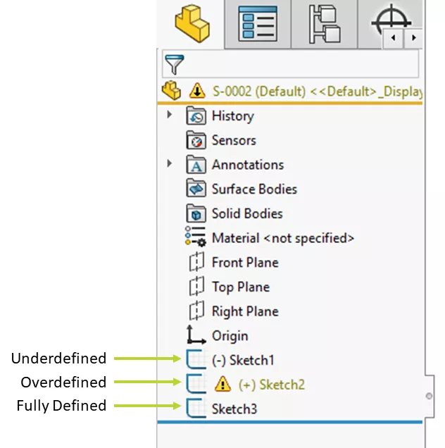
The FeatureManager uses symbols to indicate the definition of a sketch. If a sketch is underdefined, a (-) will appear next to its name in the tree. If it’s overdefined, there will be a (+), and the sketch name will typically display in yellow to show that there is a problem. A fully defined sketch won’t have any special characters. It will only display the name of the sketch and nothing more.
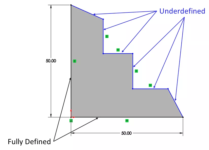
For additional granularity, SOLIDWORKS also illustrates the definition of each entity inside a sketch. In the default color scheme, blue indicates underdefined, yellow or red means overdefined, and black is fully defined. This gives you an easy way to determine where additional constraints are needed. If you see a blue entity in a sketch but can't figure out what's missing, click and drag it to see how it can move. (A vertex is often easier to drag than the line it's attached to.) This makes it clear which degrees of freedom are still available, and from there, we can decide how to lock them down.
In the picture below, note the shading inside of the sketch. This occurs when the Shaded Sketch Contours setting is enabled. If you draw a sketch profile that is bounded on all sides, it will exhibit this internal shading.
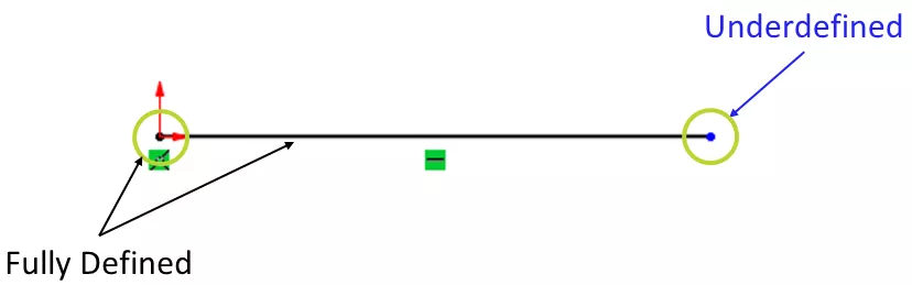
This color coding doesn’t just affect full lines. In some cases, a line may display in black while one of its endpoints appears in blue. This is the case when the orientation of a line and one of its endpoints are defined, but nothing is locking down its length.
In the example below, the line is anchored at the origin and has a Horizontal constraint, so the left endpoint and the line are considered fully defined and won’t be able to move if I drag them. However, nothing in the sketch indicates how far the right endpoint should be from the origin, so that point is considered underdefined and can slide along the horizontal. Distinctions like these are subtle but can be important to recognize when sketching.
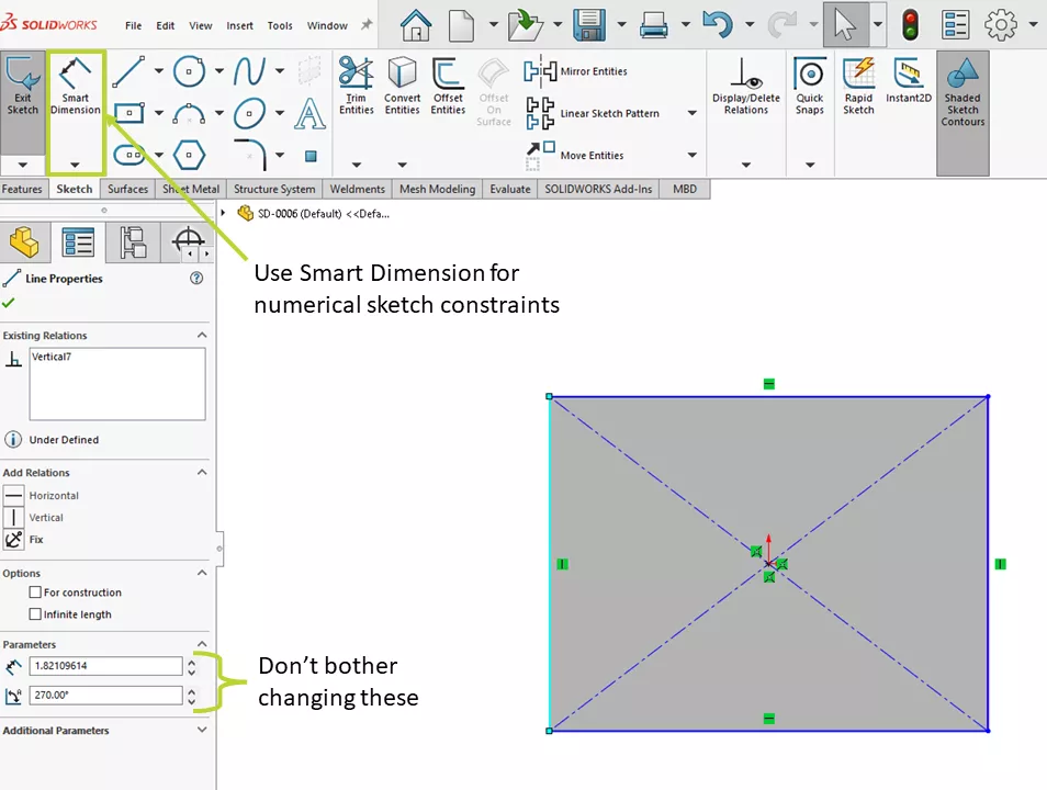
When selecting a sketch entity from the graphics area, notice that the PropertyManager on the left side of the screen has boxes for certain values related to that geometry—the length and angle of a line, the radius and center of a circle, etc.
In training classes, students will often adjust these numbers as they develop their sketches. We recommend ignoring these fields entirely. Modifying these values doesn’t add any constraints. It won’t create a dimension to lock in the value, so you’ll still be able to click and drag the geometry to alter its size or position. Whenever you need to define a numerical parameter like a distance or a diameter in a sketch, you should instead use Smart Dimension.
To be clear, you don’t necessarily need fully defined sketches. You’ll typically be able to use underdefined or even overdefined sketches to create bosses, cuts, and other features. The reason to use fully defined sketches is that they eliminate potential ambiguities in the model. You don’t want to design a part only to realize when you’re trying to fit everything together that an edge is 1.893” when it should be 2”, or that two supposedly perpendicular faces are really 87.6° apart. If you’re designing very organic, flowing geometry with complex sketches, then maybe fully defining everything with discrete values isn’t feasible. For more prismatic geometry, ensuring everything is properly constrained as you work can be a huge benefit as the design grows.
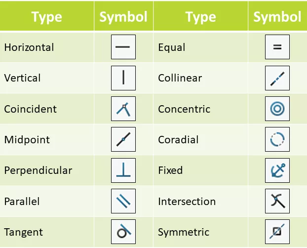
As a bonus, the table below illustrates some of the most common types of sketch relations. Over time, you'll encounter many more, but this list should at least make it easier to recognize the icons seen most often.
#4: Templates
Templates serve as a baseline of sorts for SOLIDWORKS documents. Whenever you create a new part, assembly, or drawing in SOLIDWORKS, it is generated from a template file. Any properties, settings, or even features built into the template will automatically be transferred to that new document. When getting started in SOLIDWORKS, these templates can be a good way to ensure everything is standardized across documents and between users. Setting these up early eliminates having to worry about fixing a bunch of inconsistencies somewhere down the line.
Parts, assemblies, and drawings have their own template types. To keep this section somewhat concise, we’ll focus on setting up a part template. Creating a template for an assembly is basically the same as creating one for a part. Drawings are more complex due to interactions with sheet formats, which define the title block and the borders and elements like that. See how to create a drawing template in this video. In all three cases, you’ll typically start your template design process by launching a new document, just like you would if you were creating a new model.
Document Properties and Custom Properties
The main components of a document template are document properties and custom properties. Document properties are a category of options that are tied to the document itself; they are saved with the file. When you click the Options gear icon at the top of the SOLIDWORKS window to open your settings, you’ll see a tab for System Options and a tab for Document Properties. System options are tied to your computer; these do not change from one file to another. As a result, you don’t need to worry about these when setting up a template (though you may want to explore them at some point).
Drafting Standard
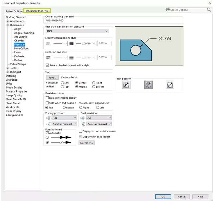
One of the most important sections of the document properties is the Drafting Standard. SOLIDWORKS comes loaded with several common drafting standards, such as ANSI, ISO, and DIN, which can drive anything from the look of your annotations to the presence of trailing zeros. You can establish a particular standard as your starting point and then customize individual categories as needed. For instance, maybe ANSI fits most of your needs, but you want the text in a diameter dimension to be aligned to the leader instead of always staying horizontal. Changes such as these can easily be made under the Drafting Standard settings.
Units
Another category to check out is the Units. This drives not only the unit system for the document but also whether to use decimals (and to how many places) or fractions. Like the Drafting Standard section, you can pick from a typical unit system like millimeter-gram-second or inch-pound-second, or you can define a custom scheme.
Image Quality
Finally, look at the Image Quality field. Image quality relates to how smooth curved edges appear on a part. When SOLIDWORKS renders a face on the screen, it has to break that face down into a mesh of triangular elements called graphics triangles. This is most noticeable when there are circular edges, as they will often look somewhat jagged. SOLIDWORKS approximates the shape of that circle by laying these triangles side by side. The image quality controls how much effort it puts into approximating that shape, so as the image quality increases, it will increase the number of triangles (and reduce their size) so that the shape looks more like a true circle.
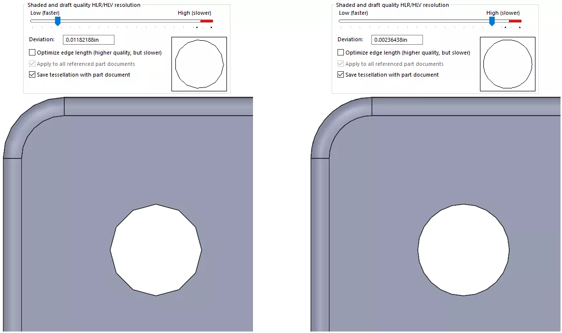
This increased resolution comes at the expense of performance. If you have a lot of curvy geometry, raising the image quality can slow down navigation operations like zooming and rotating. (This often isn’t noticeable at the part level, but if you have an assembly with many high-quality parts, it can really bog things down.) The extra triangles are typically saved with the document too, so the file size will go up. As a result, we usually recommend keeping image quality fairly low, around a quarter to a third of the way up. This should be high enough that your models will still look good but low enough that it shouldn’t hinder your ability to work efficiently.
We often see files from users struggling with assembly performance and discover that many of their components were created with unreasonably high image quality. This is why it’s important to consider these settings early on when setting up your initial templates.
There are additional document properties beyond these three categories, but Drafting Standard, Units, and Image Quality are most worthy of your attention.
Custom Properties
As previously mentioned, the other main component of a template is the custom properties. Custom properties are specific pieces of information you want to associate with the file, like the date it was created, the designer, the weight, a description, and so on. These details can be referenced in a bill of materials or in notes on a drawing, providing readers with the context they need to fully understand the model.
Open the Custom Properties dialog from the File Properties button just to the left of the Options gear at the top of the screen. When creating a template, define all the properties you think you’ll need for your models and leave the values blank. When someone goes to create a model using that template in the future, all the property names will be there; the user will just need to input the appropriate information.
It’s also possible to have SOLIDWORKS calculate values automatically. Certain properties are tracked by the program, so rather than having the user type in materials or mass by hand, the software can plug it in instead. There is a dropdown arrow on the right side of the Value/Text Expression cell that allows you to pick one of these properties.
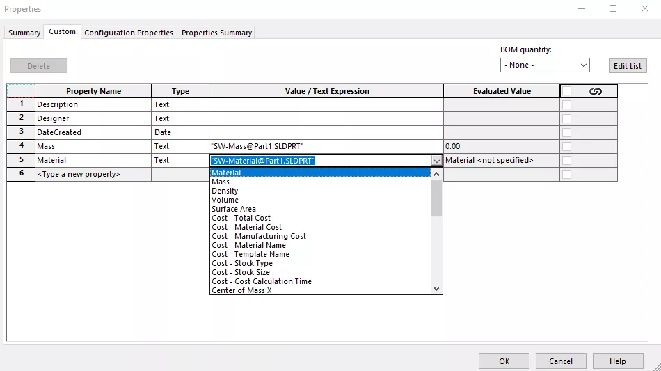
If you build multiple variations of your models in the form of configurations, you may have properties that differ from one instance to another. Instead of defining properties for the entire model, you can define them for specific configurations through the Configuration Properties tab shown in the dialog above. Any properties stored there are also saved with the template.
Once document properties and custom properties are defined as intended, you will most likely be finished. Again, you can store model features in the template, so if there is something that you want to have included in all of your designs—maybe all your parts are made off of a specific cut of sheet metal—you can create that too, but this isn’t necessarily applicable for most designers.
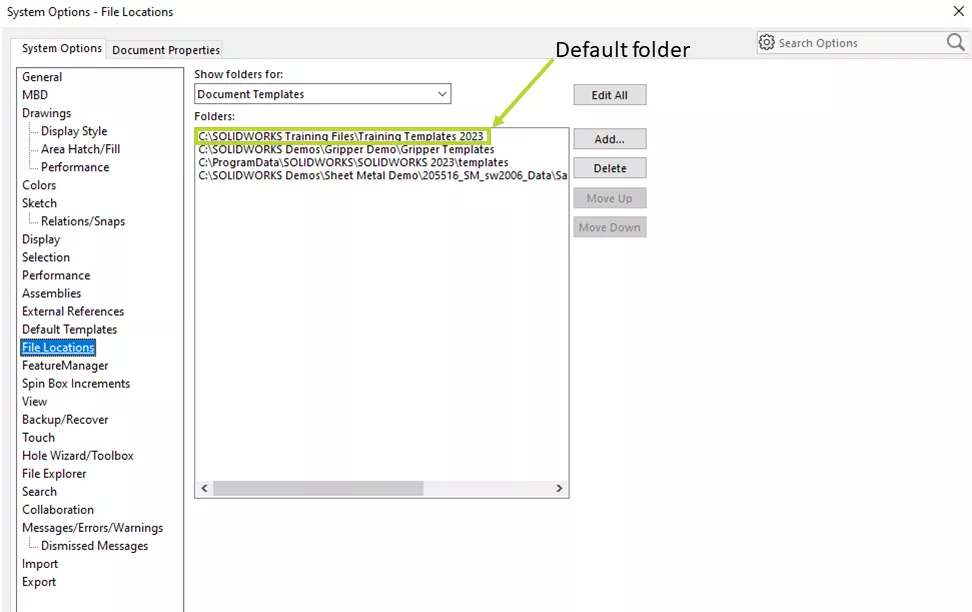
Before creating the template, determine where it should be stored. It is recommended to save any custom content like templates or design library files outside of the generic installation locations (typically “C:\Program Files\SOLIDWORKS Corp” or “C:\ProgramData\SOLIDWORKS”). This way, if you need to uninstall the software and delete those installation directories, custom data won’t be lost.
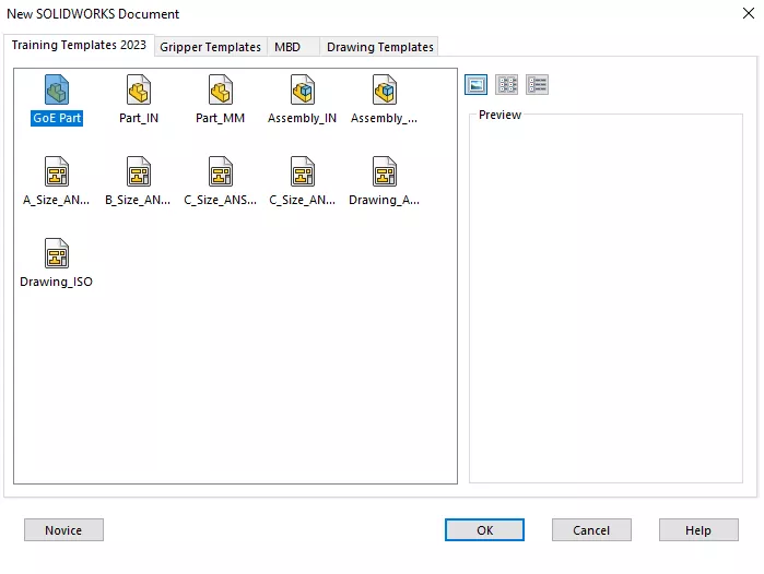
You can add the desired template directory in System Options under File Locations. Any folders identified here (and their subfolders) appear as tabs to pick from in the New dialog when creating a model. The folder at the top of the list is the default template folder, so SOLIDWORKS will automatically navigate to this directory when saving a new template.
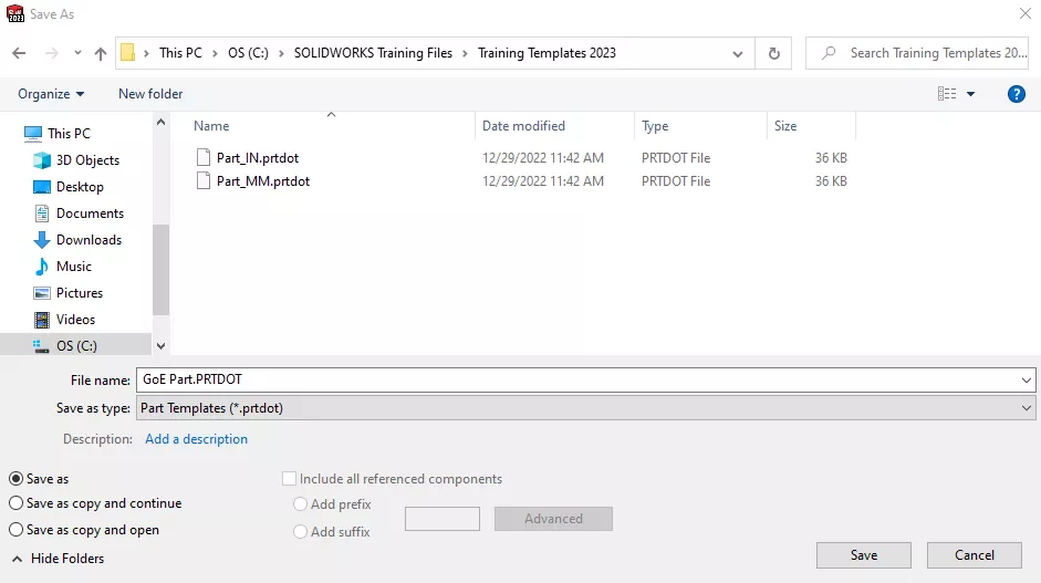
To generate a template, perform a Save As and choose the proper file type: Part Template (.prtdot), Assembly Template (.asmdot), or Drawing Template (.drwdot). It will then direct you to the default template folder where you can name it and confirm. From that point on, this template will be available when creating a new document.
While it is more admin-based rather than user-based, setting up templates is still an important early step in working with SOLIDWORKS. It allows users to establish good, consistent practices for documents from the start. It can be laborious getting everything fine-tuned, but proper template definition can certainly save time and effort in the future.
#5: Simplifications
Initially, when fitting parts into assemblies, it’s important to know that you don’t need to show every detail. Will someone be looking closely enough to see that a screw doesn’t have threads on it? Does it make a difference in the big picture if some components inside a sealed enclosure aren’t being displayed? Simplifying components and removing unnecessary details can be a great way to improve design performance.
We frequently hear from customers dealing with long open times or severe sluggishness on large assemblies or drawings. Upon further inspection of the model, we'll often find that they've included all possible components down to the smallest fasteners. It's important to recognize that SOLIDWORKS and your computer have their limits, so there are going to be times when what you want the program to do just can’t be achieved quickly.
To be fair, if you work primarily on smaller assemblies, this may not be anything you need to worry about, but if your models have hundreds or thousands of components, you may want to be proactive in your designs.
Configurations
Configurations can be very helpful when it comes to simplifying your models. Configurations enable you to store multiple versions of a model in a single file, so you can maintain a less-detailed version alongside the full one if you want to have easy access to both. There are a lot of effective tools to help you create these simplified configurations, including Simplify, Defeature, and SpeedPak. However, it’s also easy to create these manually by suppressing features from the FeatureManager design tree.
In a part model, look for features that don’t add to the overall function of the component or that would be hidden or insignificant at the scale of the assembly. Fillets, text, logos, and threads are good examples to target. Just be careful about parent-child relationships. If you suppress a feature that was referenced by others further down the tree, those later features will be suppressed as well. Alternatively, instead of suppressing features, it might make sense to cover up features. For example, you can extrude an equally sized cylinder over a helical spring to drastically reduce its graphical complexity while maintaining its geometric footprint in the assembly. You can have the boss active in the simplified configuration and suppressed in the standard one.
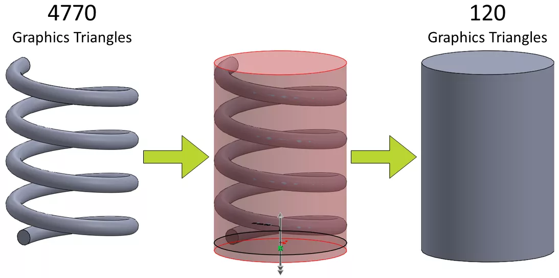
Another option for springs is to model them with a single revolution. Instead of completely blocking out the geometry with a boss, you can simplify the spring by creating a configuration with just one turn while maintaining the correct height and diameter. This way, you still get the nice visual of a coil but with reduced complexity. Working with the same model shown above, the triangle count decreased from 4770 to 1312, so there was still a meaningful improvement.
In an assembly model, you can create a separate configuration that references all the simplified part configurations you’ve created. Any components that don’t add significant value to the overall assembly can also be suppressed in this configuration, reducing the amount of data even further.
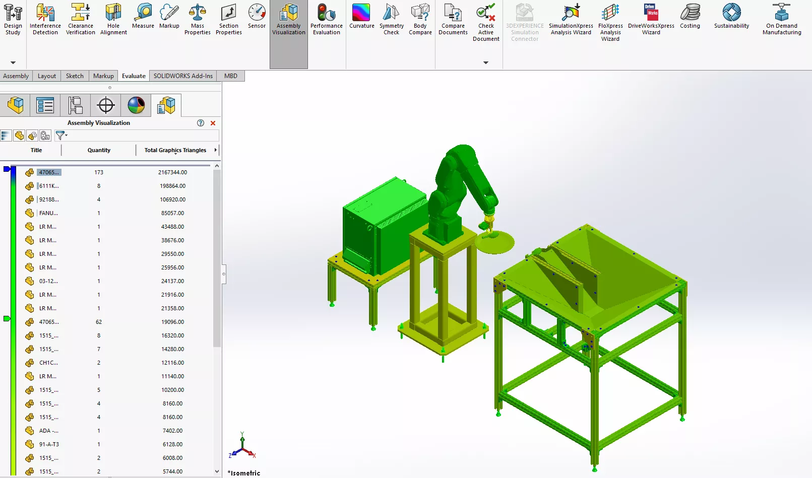
Assembly Visualization
As I mentioned, the goal is to be proactive so that you can avoid getting stuck with performance issues, but if you do need to be reactive there’s a great tool called Assembly Visualization that can help identify models that might be slowing you down. Assembly Visualization essentially ranks and color-codes all the components in an assembly based on a particular parameter, like mass, open time, or quantity. You can also sort components by their graphics triangle count, either the amount for a single instance or the total for however many instances exist in the assembly. This makes it easy to determine which components should be simplified first to have the greatest impact on the model.
Again, not everyone needs to worry about reducing detail in their designs. If you have a powerful computer and don’t make very complex assemblies, you may be able to get away with showing your components in full form. Being aware of these simplification tools early on in your SOLIDWORKS journey will help you determine what to do when problems arise or, better yet, how to circumvent them entirely.
Suggested Article >> Best Workstations for SOLIDWORKS: Hardware Configurations
#6: Resources
You absolutely do not have to go it alone with SOLIDWORKS. There are plenty of easily accessible resources to help you dig deeper into the software.
Training
GoEngineer offers a wide variety of training courses for SOLIDWORKS through in-person, virtual, and self-paced formats. The SOLIDWORKS Essentials class is the perfect starting point for just about every user getting started, and beyond that, there are sessions in more advanced topics like assemblies, sheet metal, and surfacing.
Outside of formal training, you can also find tons of free resources online and within the software.

The GoEngineer Community is a free forum built by engineers, for engineers. When you join, you have access to hundreds of industry experts and can connect with others in the engineering community. Ask questions, offer advice, read technical articles, and see upcoming online and in-person events for all things SOLIDWORKS, 3DEXPERIENCE, and other services offered by GoEngineer.
MySolidWorks also includes videos exploring individual features in-depth, such as sweeps, fillets, and equations. There are also lessons on other tools in the SOLIDWORKS portfolio, like Simulation, CAM, and Visualize. Many of these videos are free to anyone with an active subscription (and some don’t even require that). Another vital area of MySolidWorks is the SolidPractices library. These documents provide exceptional “best practices”-type information for topics related to SOLIDWORKS CAD, Electrical, Simulation, PDM, and more. These papers are typically written by resellers like GoEngineer or by SOLIDWORKS employees themselves, so you can be confident the information is reliable.
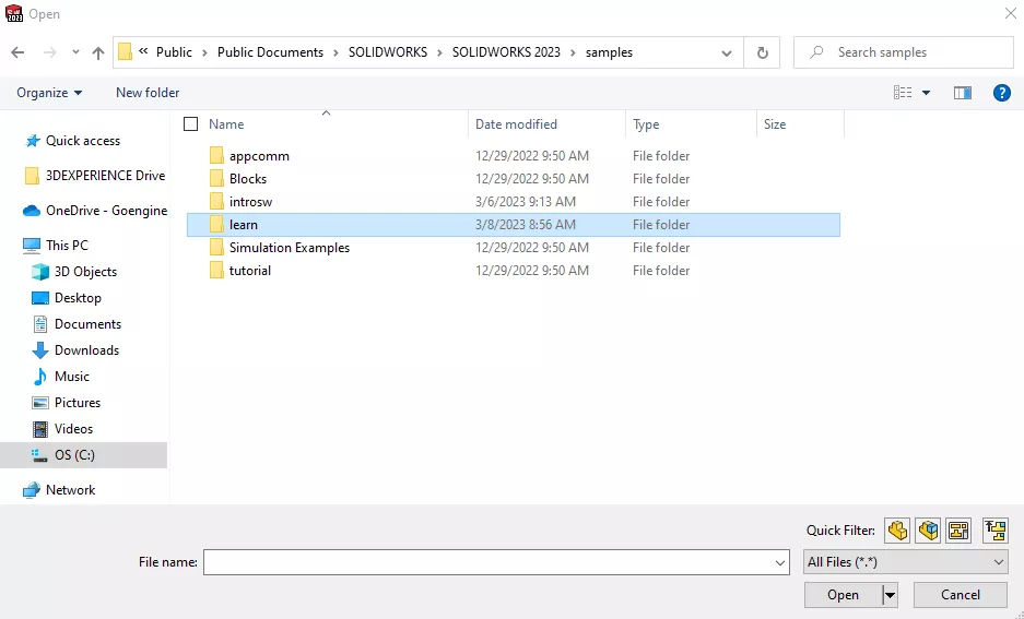
Sample Files in SOLIDWORKS
Inside the software, there are sample files that can offer some inspiration for your own designs. On the Welcome dialog that appears when you launch SOLIDWORKS, switch to the Learn tab at the top to find these samples. The interface differs from one version to the next, but the image below is from SOLIDWORKS 2023.
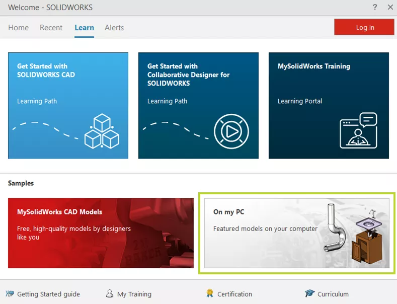
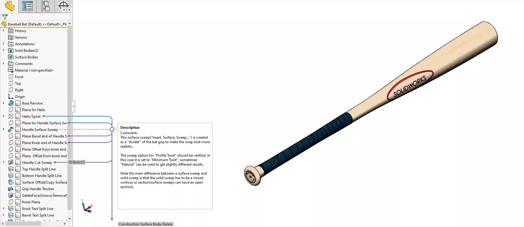
The sample files are stored locally on your computer, and, like the dialog from which they came, there may be different models available depending on your installation. In SOLIDWORKS 2023, there is a subfolder called “learn” that includes a lot of interesting applications for complex techniques, especially surfacing. The best part is that these “learn” files have comments on nearly every feature to explain what that feature does in the context of the overall design.
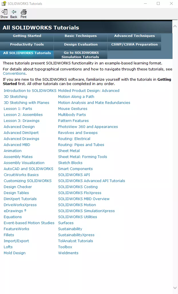
Help Menu
And don’t forget about the Tutorials found in the Help menu. Upon opening, the Tutorials window will display only a small sample of the full catalog—a specific group meant to expose you to some of the fundamental capabilities in SOLIDWORKS. These are certainly a good start, but there are many other subjects to help you develop your skills further. Click the All SOLIDWORKS Tutorials button for a full list, including advanced topics like 3D sketching, lofts, mold design, and routing.
Help Documents
Another way to learn about new commands is the Help documentation. This extensive guide explains not only all the commands, but also options, add-ins, and just about every other aspect of SOLIDWORKS. On the left side of the page are several categories to sort through or use the Search bar in the upper-right corner to see everything that pertains to a specific term or phrase.
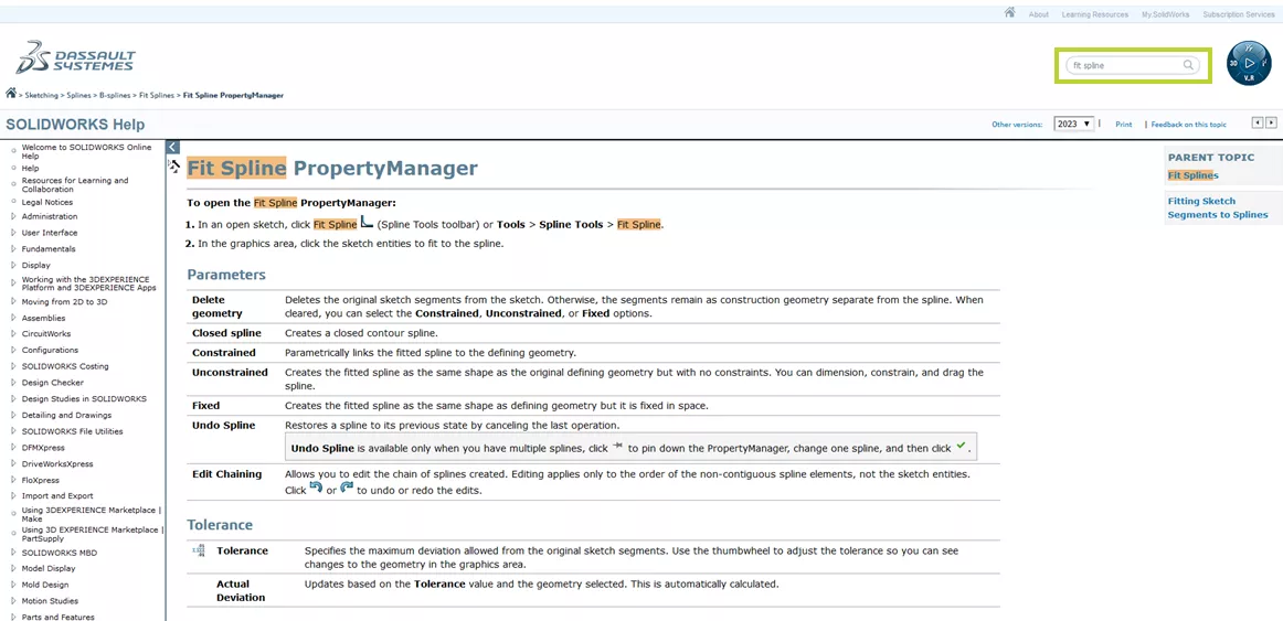
Most commands have multiple Help guide pages that explain the purpose of a command, certain characteristics of it, and the function of each field in its PropertyManager. This PropertyManager breakdown is helpful because it’s often not obvious how a specific checkbox or value might impact a feature.
To access the Help documents, go to the Help dropdown menu inside SOLIDWORKS. If the Use Web Help option is turned on, it will launch the page in an Internet browser. Since these help documents are online, they can be found in a Google search or web browser as well.
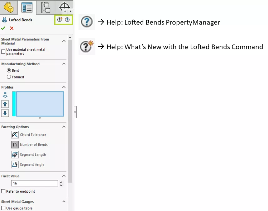
Help information about a particular command can also be opened directly from the command's PropertyManager. In the top-right corner of the PropertyManager, there are often one or two question mark icons that link to the Help documentation. The standard question mark is light blue and will bring you to the page that explains that tool’s PropertyManager. If the command you’re looking at was enhanced in that year of SOLIDWORKS, a black question mark with an asterisk will be available. This will bring you to a page that explains how the command has changed.
We hope this makes it clear that there are many ways to learn SOLIDWORKS! You can take formal, multi-day classes through GoEngineer; you can use MySolidWorks to review quick videos and playlists or to read about best practices; or you can reference elements inside the software like sample files, tutorials, and the Help guide. There is also all the content available in blogs, on YouTube, or in forums. Given the millions of people who use SOLIDWORKS on a regular basis, it's very likely that someone else has already asked or answered many of your questions. By taking advantage of all these resources, you’ll be able to steadily expand your skill set and master the art of SOLIDWORKS.
#7: Practice
As is often the case when trying something new, practice is essential to your progress with SOLIDWORKS. It’s very easy to forget what you’ve learned if there are large gaps in your usage of the software.
If you have some free time, try modeling objects in the room around you. Don’t get hung up on realistic dimensions or anything like that. Just try to get the proportions right. This kind of conceptual challenge is a fun way to sharpen your design approach.
If you really enjoy using SOLIDWORKS and want to spend more time with it, consider getting access on your personal computer. The 3DEXPERIENCE SOLIDWORKS for Makers offer provides users SOLIDWORKS Professional, two cloud design apps, rendering tools, and CAM programming capabilities for $99 a year. It can be a fantastic option if you’re looking to use SOLIDWORKS in more of a hobbyist capacity.
You absolutely cannot learn SOLIDWORKS all at once. The learning process is continual, so try finding opportunities to design as often as you can. SOLIDWORKS is an expansive landscape, but by regularly exploring and experimenting, you’ll be able to make it feel smaller.

SOLIDWORKS CAD Cheat Sheet
Our SOLIDWORKS CAD Cheat Sheet, featuring over 90 tips and tricks, will help speed up your process.
Learn More About SOLIDWORKS
SOLIDWORKS Dimensions Dialog Box Options
SOLIDWORKS Tutorial: Edit, Create, & Convert Style Splines
How to Open Large Assemblies in SOLIDWORKS
SOLIDWORKS Weldments: Corners, Gussets, & Bounding Box
![]()
About GoEngineer
GoEngineer delivers software, technology, and expertise that enable companies to unlock design innovation and deliver better products faster. With more than 40 years of experience and tens of thousands of customers in high tech, medical, machine design, energy and other industries, GoEngineer provides best-in-class design solutions from SOLIDWORKS CAD, Stratasys 3D printing, Creaform & Artec 3D scanning, CAMWorks, PLM, and more
Get our wide array of technical resources delivered right to your inbox.
Unsubscribe at any time.