Intro to CAD-Connected Composites FEA: A Game-Changer for Composites Design
Composite Analysis functionality has long been enabled by powerful solvers like Abaqus, and the foremost composites design tool is CATIA V5 (or 3DEXPERIENCE CATIA). Both solutions are industry leaders, and the advent of the 3DEXPERIENCE Platform has enabled these functionalities to be merged into a single solution for a Modeling and Simulation (MODSIM) unified workflow for all of your composites needs. This article focuses on composites analysis on the 3DEXPERIENCE Platform and is meant to be an add-on to the CATIA composites design blog here.
Why Simulate Composite Materials?
Composites are one of the most popular materials in nearly any industry where high-strength and lightweight designs are crucial, including aerospace, automotive, consumer goods, and even the medical field. To innovate in these fast-paced fields, simply using composites is not enough. The composite structures must be validated and tested for performance; this is where simulation comes in.
Developing tooling or prototypes of composite structures is costly, making validation via destructive testing much less appealing. In many cases, it is easier to simulate the structure early in the design phase to reduce the need for physical testing.
Why is Composite Simulation Hard?
Traditional layup or unidirectional tape composite structures are orthotropic or anisotropic in nature. Simply put, this means that the rigidity of the material is dissimilar in different directions and can also be different in tension and compression as well.
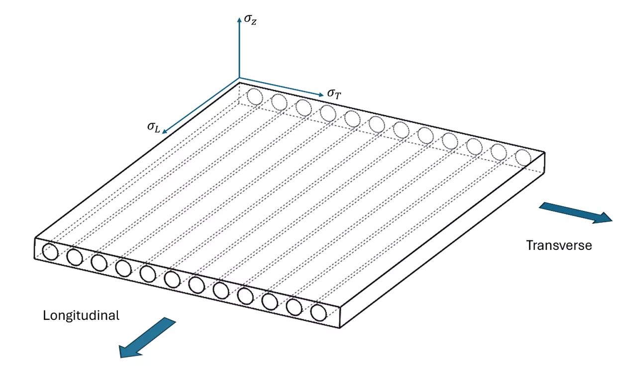
This proves uniquely difficult for simulation. Most of the material data for Finite Element Analysis (FEA) is derived from uniaxial tension tests where the material is stretched, and the load is measured in tandem with the amount the material deforms. This generates a stress-strain curve that can be used for simulation.
In the case of composites, each design will have its own layup stack, which means that each design could need at least three separate physical tests to characterize the material. This has traditionally made material characterization of composite structures unattainable for many smaller companies.
This blog will demonstrate how 3DEXPERIENCE is changing this landscape with powerful integration of composite design and analysis under one roof.
Powerful FEA tools like Abaqus have a long history of accurate composite analysis. This is enabled by a few key technologies.
First, let's discuss the most difficult part of modeling any composite structure - correctly modeling the material behavior.
Macroscopic Material Modeling
Abaqus and 3DEXPERIENCE SIMULATION can allow for fully anisotropic material behavior on a macroscopic scale. This means that the composite material is modeled as a homogeneous material with stiffness properties that change based on the direction of loading. These tools allow the user to define the composite layup material properties inside the simulation tool in a variety of ways according to their needs. These four types of anisotropic elasticity are:
- Orthotropic material properties can be entered by entering elastic modulus, shear modulus, and poison’s ratio in all three orthotropic directions.
- Lamina Properties can be entered as a plane stress formulation using just in-plane and transverse properties for elasticity, a single poison’s ratio, and shear modulus in all three directions (most commonly used for laminated shells).
- Perfectly orthotropic materials must explicitly define all nonzero terms in the orthotropic material matrix.
- Perfectly anisotropic materials must explicitly define all nonzero terms in the anisotropic material matrix.
3DEXPERIENCE allows us to map the composite design data from CATIA for a direct link to draping, fiber orientation, and layup information, which allows for the complex structural matrix to be computed for you (more on this later).
Micromechanics Material Modeling
With this approach, the fiber and matrix reinforcement materials are modeled separately as deformable bodies. Though this method will likely produce the most robust results, modeling every fiber of a composite structure individually and simulating contact interactions between those fibers and the composite matrix quickly becomes too computationally demanding to be viable on any meaningful scale.
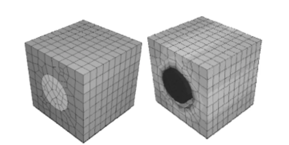
Unit cell of a fiber-matrix delamination. Image courtesy of Dassault Systèmes™
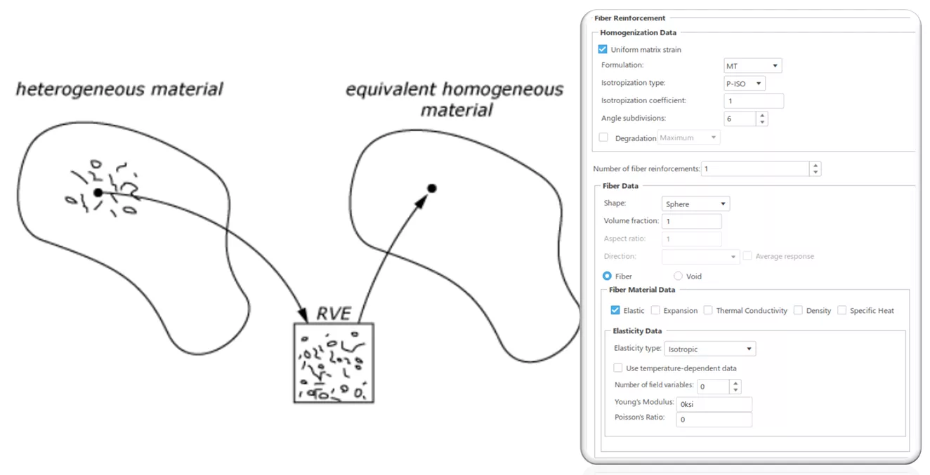
In 3DEXPERIENCE SIMULATION, the user can instead dictate fiber reinforcement parameters that, when combined, create a Representative Volume Element (RVE) of the composite material and extrapolate that small volume to determine the material characteristics of the larger scale composite structure. This allows the user to quickly and easily define complex composite material properties by entering a few simple parameters.
Damage Models
Composite failure generally happens in one of two failure modes. Either there is a failure in individual plies (layers) due to excess tension, compression, or shear, or there is delamination between the plies themselves.
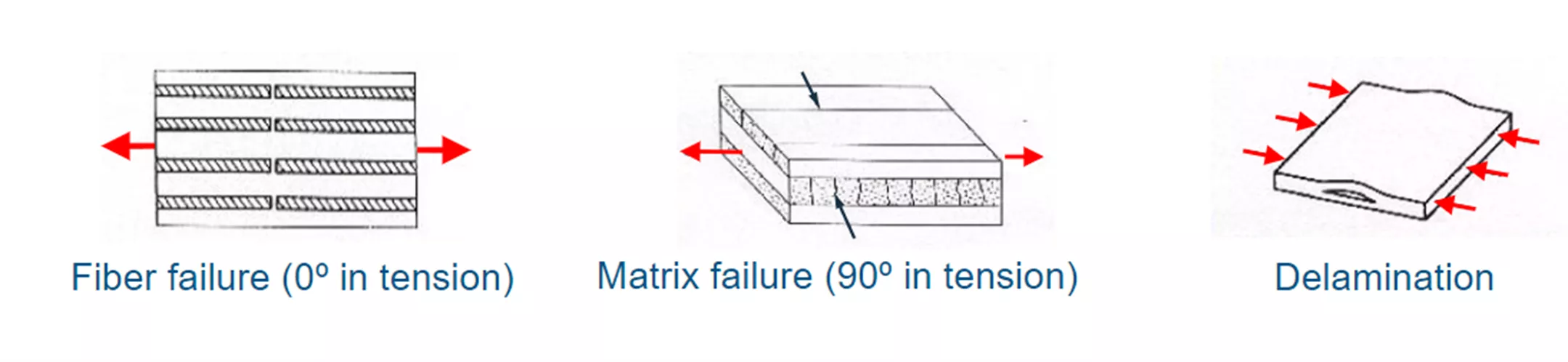
Image courtesy of Dassault Systèmes™
3DEXPERIENCE SIMULATION has the capability to model the moment of failure in any given ply. This damage initiation parameter can be defined in one of a few ways:
- Maximum Stress Theory - Simple stress-based failure criteria that measure each component of directional stress and compare it against a defined stress limit. This theory provides no interaction between different directions of the stress components, so accuracy is limited.
- Maximum Strain Theory - A simple strain-based failure criteria that measures directional strain components against defined limits.
- Tsai-Hill Theory - This model is an extension of the Hill yield criterion model developed by Rodney Hill. The Tsai-Hill failure criterion is a simple model used to predict failure in the composite lamina.
- Tsai-Wu Theory - This failure model was introduced later to smoothen the form of the Tsai-Hill criteria. This model can provide more accurate results than Tsai-Hill when compared to experimental data, but the difference is usually not large.
Mixed Modeling
These two basic failure modes are further complicated by the fact that failure does not always occur in one of the extreme (inside/outside) layers of the composite. Therefore, all layers need to be modeled discretely. To account for this, 3DEXPERIENCE SIMULATION uses a mixed modeling formulation of the composite structure. Each individual ply is characterized by one of the anisotropic methods listed above, and then stacked according to the design of the structure. This allows for a very robust stiffness representation that is driven by the composite’s design process.
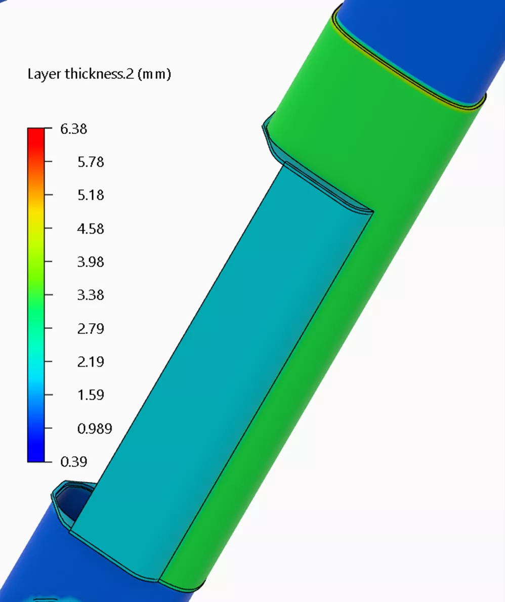
Nonuniform Thickness Shells
Most composite structures are very thin relative to their major dimensions, meaning it is advantageous to use shell elements to increase solver efficiency. However, lots of composite structures may have additional layup layers in areas of high stress to reduce the likelihood of failure. Many simulation tools assume that a shell element has a single, uniform thickness throughout the body, but this is not the case with Abaqs and 3DEXPERIENCE SIMULATION. Shell thicknesses can be mapped to user-created spatial data, or even be linked to the CATIA 3D CAD geometry itself.
Design Link
Dassault Systèmes™ is an industry leader in composites design tools and Finite Element Analysis tools. For many years, these tools existed in disconnected silos. The 3DEXPERIENCE Platform has revolutionized the industry by linking composite designers and analysts. Designers can use the world-class CATIA composite design functionality and route the layered composite material definition directly to the simulation tools powered by the Abaqus solver.
How It Works
A designer using the CATIA Composites Design app can complete their layup design using any of the methodologies discussed by my colleague Tim in his article here. The materials involved in the composite design domain can be characterized as unidirectional, bidirectional, non-crimp fabric, or non-structural. These materials also include cured and uncured thickness ratios, deformation limits, and other variables. Most crucial for simulation are the directionality definitions, as these affect the anisotropic stiffness definition.
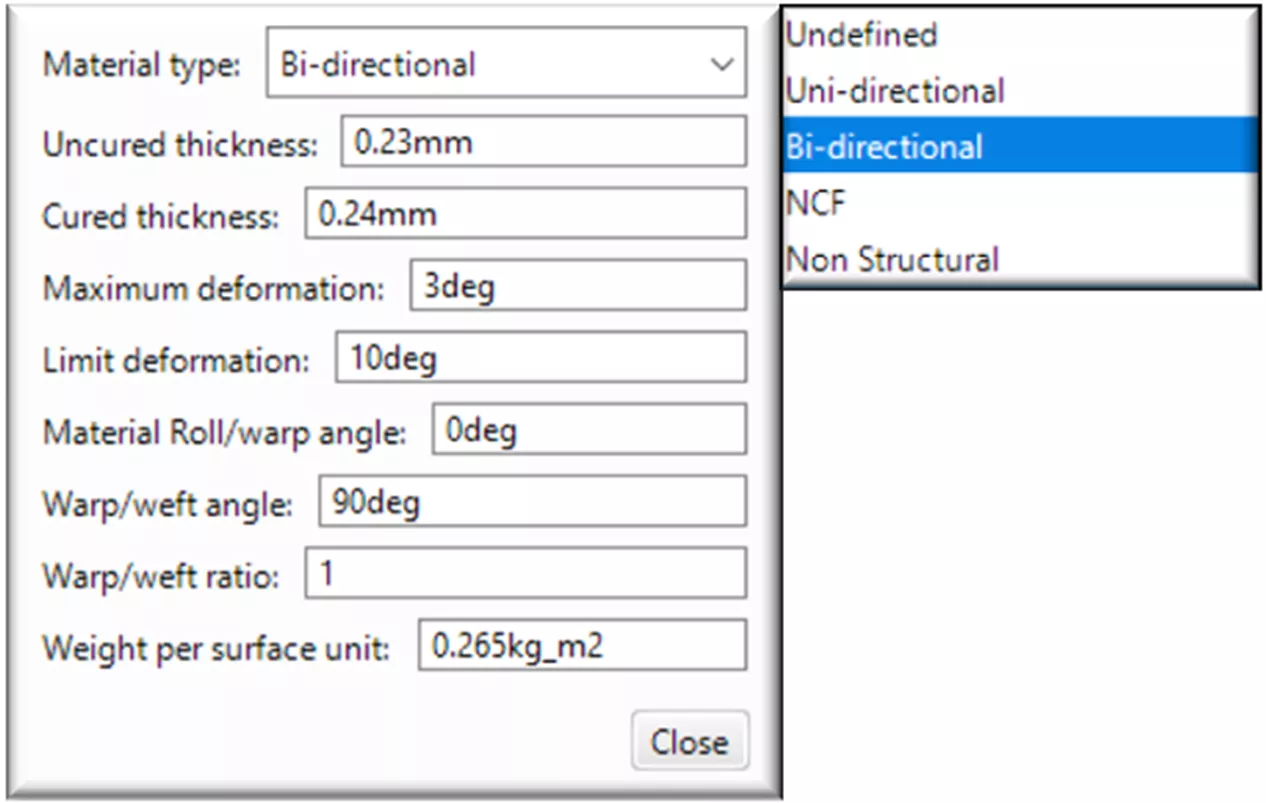
From there, the individual materials are connected to simulation parameters by “rerouting” the material link, which combines the composite domain material definition with simulation domain material properties.
From there, the analyst can link to the correct composite properties, as discussed earlier. Here is an example of a composite material definition for simulation. This re-routing of the material link is only necessary for the initial setup of the model. Any changes to geometry, plies, layers, or orientation will be updated accordingly.
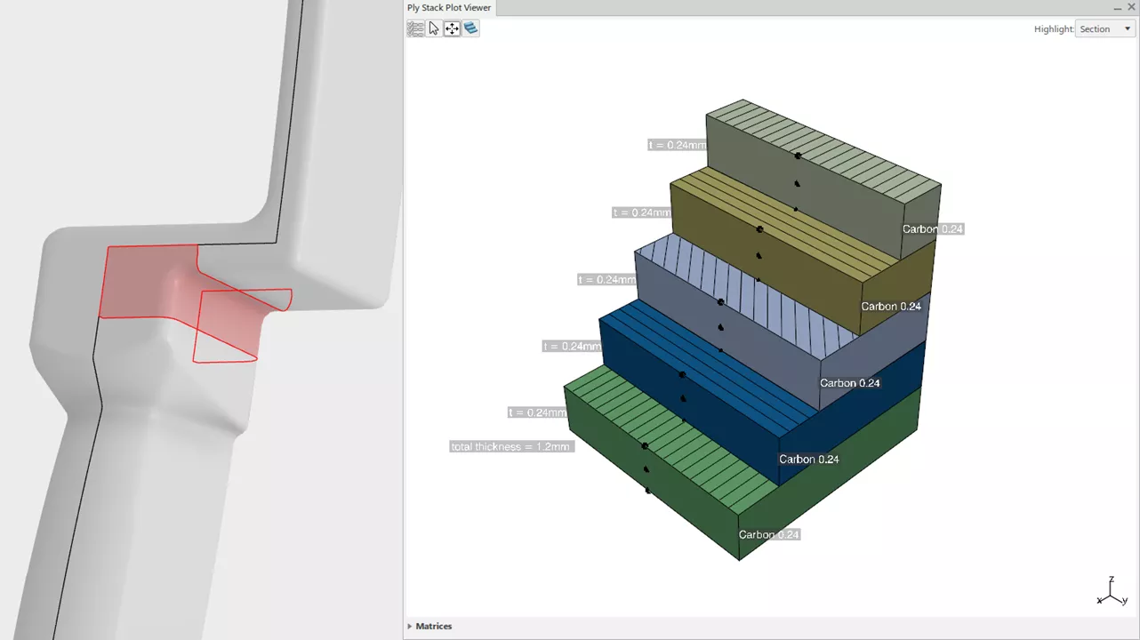
The next step is to combine the geometric definition of the composites with the material properties created above. This is done through a section definition in the Structural Model Creation app.
Choosing a body with composite design information allows the user to select a variety of ways to map the composite layup information onto the structural mesh, whichever is most appropriate for the design workflow used.
This one box is the main differentiator between 3DEXPERIENCE and other composite design and analysis solutions. The ability to predict draping, warping, and other imperfections stemming from composite manufacturing and then MAP those imperfections to a structural model for finite element analysis is a game changer for anyone working with layered composite structures.
From here, the setup of the FEA model is no different than it would be with any other material. Leveraging the fantastic Abaqus solver allows the user to solve anything from a basic static or resonant frequency analysis up to explicit dynamic impact or drop test studies.
The 3DEXPERIENCE Platform is truly innovating and leading the charge in the integration of 3D modeling and simulation design processes, or MODSIM for short. This article serves only as one example of this innovation, and there are many more.
For more information on this capability or other advanced features of 3DEXPERIENCE, reach out to GoEngineer. If you'd like composites analysis provided to you as a service, our simulation consulting team is happy to help.
Learn how to raise the bar and stay competitive in SOLIDWORKS and beyond here.
Related Articles
Composites in 3DEXPERIENCE CATIA Overview
6 Design Struggles in SOLIDWORKS that are Easier in CATIA
CATIA V5 vs 3DEXPERIENCE CATIA: Interface, Licensing, Installation, & Setup
CATIA V5 Parametric Optimization Guide
Abaqus and CATIA Now Available from GoEngineer: NOT Just for Enterprise!

About Matt Sherak
Matt Sherak is a Sr. Simulation Product Specialist with GoEngineer and is based out of Denver, Colorado. He graduated from Metropolitan State University of Denver in 2015 with a focus on Mechanical Engineering and Advanced Manufacturing. After a brief time working with avionics installation, he moved on to work in the Simulation field as a simulation- focused engineer.
Get our wide array of technical resources delivered right to your inbox.
Unsubscribe at any time.