SOLIDWORKS 2020 Structure Systems for Weldments
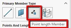
In 2019, SOLIDWORKS introduced Structure Systems for Weldments. Structure systems are used to quickly model a structure using weldment profiles and sketch geometry. When using Structure systems, you start with Primary members and then use Secondary Members to connect the Primary members. The changes made in SOLIDWORKS 2020 Structure Systems pertain to the Primary members, Point length Members. In 2019 for the Point Length Member option you would select sketch points/entities that you would like to extrude your profile (normal to the plane) and up to a set length.
In the 2020 release, you have three new options (not including the existing length) for end conditions when using Point Length Member as the Primary Member. As you can see in fig. 1 the end conditions are length, point, up to point, and up to plane.
End Condition Descriptions
Point
- Extends a primary member from the start point to the endpoint. Click Chain Link to add members along a chain of points
Up to Point
- Extends a primary member up to the selected point
Up to Plane
- Extends a primary member from a point to a plane. The members extrude in the directions of the reference plane. You can also reverse the direction.
End conditions can be applied from basic sketch geometry
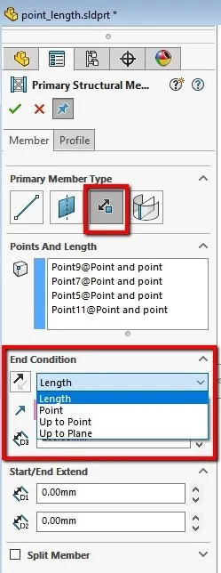
Figure 1.
In fig. 2-5 you can see how each one of the end conditions can be applied from basic sketch geometry.
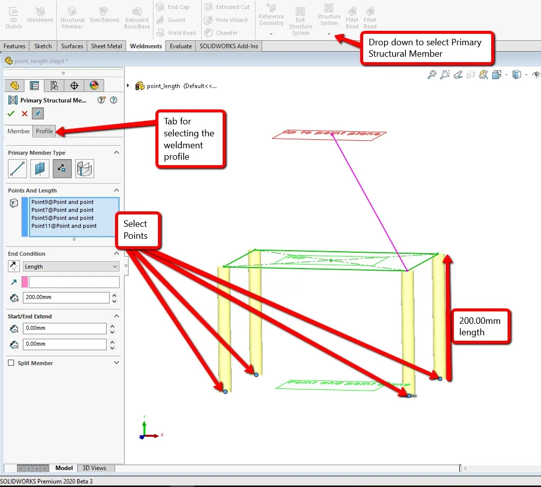
Fig. 2 is representing the original end condition for Point and Length as a Primary Member. The intended use is to select sketch points, reference points, or vertices and then you input a length and select profile to extrude.
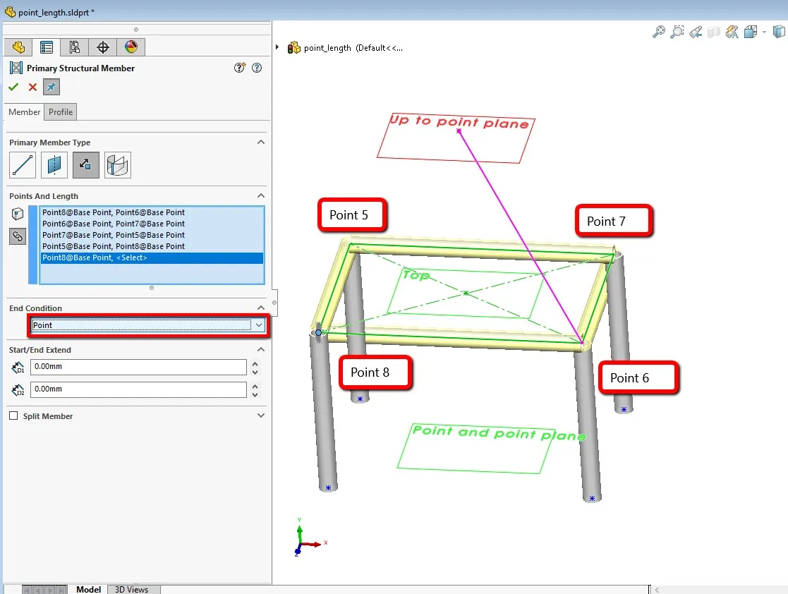
Fig. 3 represents the end condition of Point. In this example, one of the corner sketch points is selected, and then moving around the rectangle you select the remaining 3 points to create an extruded weldment profile to link all the corners together.
Up to point is displayed in fig. 4. This end condition takes advantage of selecting a single point that you would like all your profiles to meet at that have a starting point.
Fig. 5 shows the added feature to length end condition. The user starts by selecting a point and then either using a destination point or sketch line you select either one in the Direction of Extrusion box. The user will still need to input a length for the extrusion.
Primary Members Based on Point and Length (fig. 2)
Extruded weldment profile – Primary Members Between Points (fig. 3)
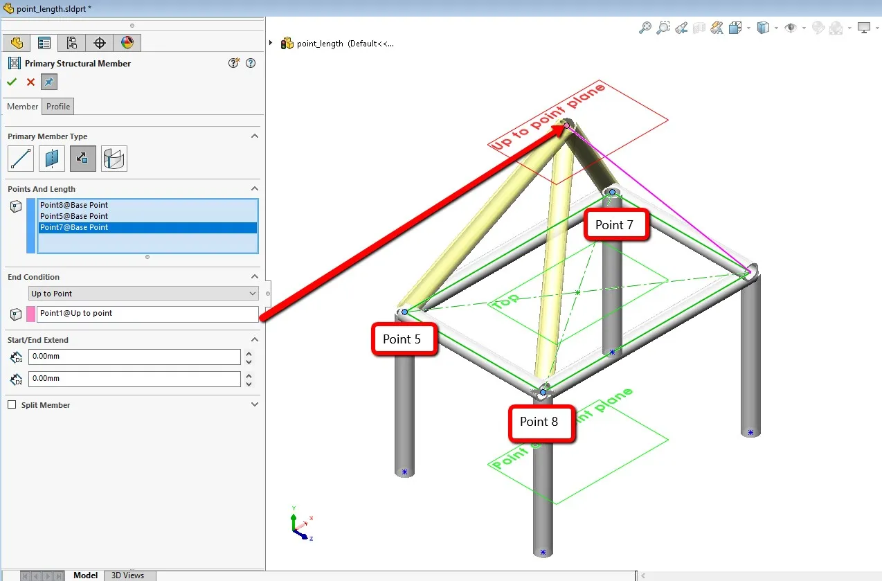
Selecting a single point – Primary Members Based on Up to Point (fig. 4)
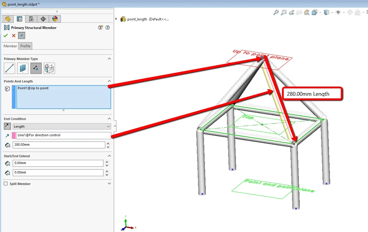
End Condition – Primary Members Based on Point and Length Direction (fig. 5)
Interested in learning more about what’s new in SOLIDWORKS 2020, check out our collection of videos here.

About Alek Cook
Alek was introduced to SOLIDWORKS during college at Arizona State University pursing Aerospace Engineering. Among that coursework, he used SOLIDWORKS to design a product for a NASA competition and senior design. Alek has spent 5 years in the metal fabrication industry and enjoys designing home renovations and personal projects in SOLIDWORKS.
Get our wide array of technical resources delivered right to your inbox.
Unsubscribe at any time.