Cybertruck Simulation: Deal or Dud?
Figure 1 – Transient Animation of Cybertruck Flow Development
News of Tesla’s Cybertruck was released on Friday, November 22nd and the internet was divided. Through all the buzz we wanted to help people make up their mind on whether or not this truck is a deal or a dud. Let’s explore the aerodynamic performance of the Cybertruck with SOLIDWORKS Flow Simulation and let the results speak for themselves.
Modeling the Cybertruck and other variations in CAD
It’s important to understand the CAD model to understand the assumptions involved in our Cybertruck simulation. Our model didn’t come directly from Tesla. Through the use of dimensions provided in Tesla’s release presentation and some frontal and profile photos/renderings on the internet, we constructed a 3D model of Tesla’s Cybertruck.
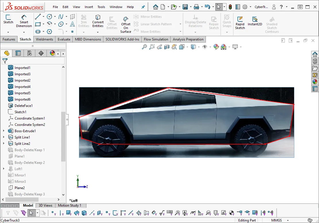
Figure 2 – Cybertruck SOLIDWORKS CAD Construction
There were plenty of images available on the internet, so we were able to compare important facets of our reproduction to Tesla’s original to try to model the aerodynamically relevant features.
From this model, we introduced other variations of the Cybertruck. One with an open bed, and another without the side fairings which, strangely, actually looks like a truck (don’t mind the glass) .
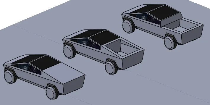
Figure 3 – Cybertruck variations. Left to right: closed bed, open bed, no fairings
For comparison, we downloaded a CAD model of a competitor product (Chevy Silverado) from an online database. This file took a lot of work to clean-up and special thanks to my colleague Arun for working late to take this on.
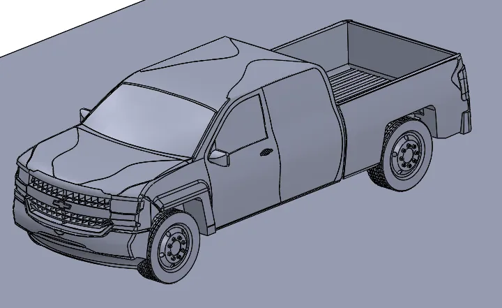
Figure 4 – Chevy Silverado Model
Finally, we introduced two other “vehicles” to measure the extremes. In this case a streamlined teardrop design and a simple rectangular box.
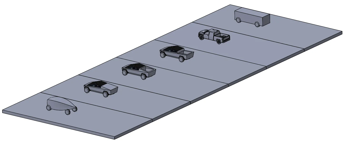
Figure 5 – The competitors. Streamlined model on far left and simple box on the far right.
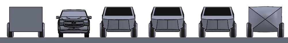
Figure 6 – Same frontal areas. Note: Silverado frontal area slightly smaller than other vehicles.
Cybertruck FLOW Simulation results
We set up all the vehicles to run side-by-side at typical expressway speeds of 70mph. This is simulated in SOLIDWORKS Flow Simulation as a sort of “virtual wind tunnel” but with additional inputs for ground movement and tire rotation. Here were some of the relevant results.
Turbulence
This first animation shows the general “wind tunnel” with the turbulent energy shown trailing each truck. Wherever there is turbulence generated, there will be drag. Energy lost due to turbulence will cause average pressure acting on the rear surfaces to be much lower than the forward surfaces, leading to a net force acting against the vehicle’s motion.
Figure 7 – Flow Field animation
The next image shows turbulent energy isosurfaces. You can see the largest amount of turbulence on the box body and the smallest amount on the streamline body, but it’s difficult to make-out the precise difference between the truck models.
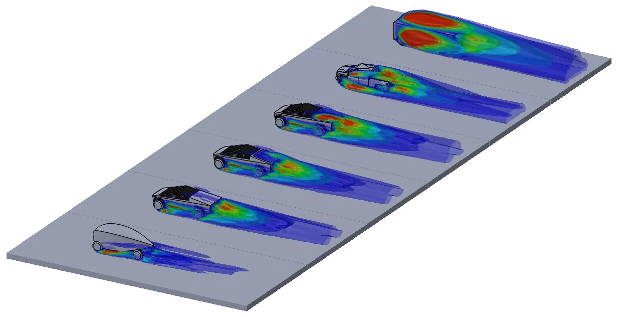
Figure 8 – Turbulent Energy Isosurfaces
Here’s a closer look at the Cybertruck open bed compared to the Silverado. Which one do you think generates more turbulent energy?
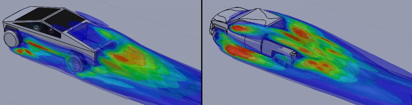
Figure 9 – Open Bed vs. Silverado
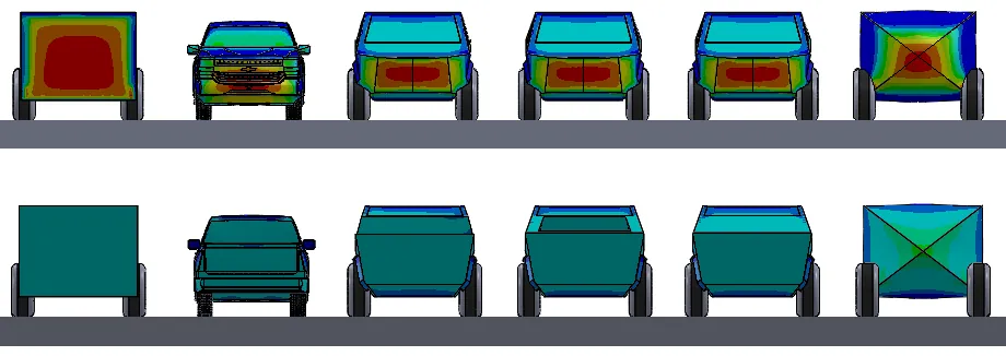
Pressure Profiles
If we compare the pressures acting on the front and rear surfaces, we can see the differential in the average colors should give us the overall drag. You can see, for example, the streamlined body (on the right) has some relatively low pressures on its front projection and higher pressures on its back projection compared to the other vehicles.
Drag Results
From here, the software does the
rest of the work to calculate the overall drag force, and here were the
results:
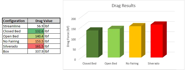
Figure 11 – Drag Force Results
I almost couldn’t believe the prismatic Cybertruck even without its side fairings would show better drag results than the old Silverado.
Get more information about SOLIDWORKS Flow Simulation
SOLIDWORKS Flow Simulation is a CFD software designed for the everyday SOLIDWORKS user and analyst. Talk to a GoEngineer sales representative to learn more about professional versions, get pricing, and understand how it can impact your business. Let’s Talk

About Shaun Bentley
Shaun Bentley is passionate about applied mathematics and engineering, which led him to pursue and understand real world applications of FEA, CFD, kinematics, dynamics, and 3D & 2D modeling. He teaches many simulation classes to both new and advanced users attending training at GoEngineer. Since 2006, Shaun has been working with simulation tools to solve real world engineering problems. With every new project, he seeks to find ways to push simulation to its uppermost limits, even going so far as to write bespoke code and macros. He has passed the Michigan FE exam and mentors or consults for virtually any industry that uses SOLIDWORKS, especially automotive and automated tools. He is a speed 3D modeling champion and one of the first Certified SOLIDWORKS Experts in Simulation in the world.
Get our wide array of technical resources delivered right to your inbox.
Unsubscribe at any time.