There are many occasions that will require engraving on curved surfaces and if you haven’t done it before it can be a bit confusing. We will go step by step on the process of creating a Curve Project feature.
- Sketch Annotation
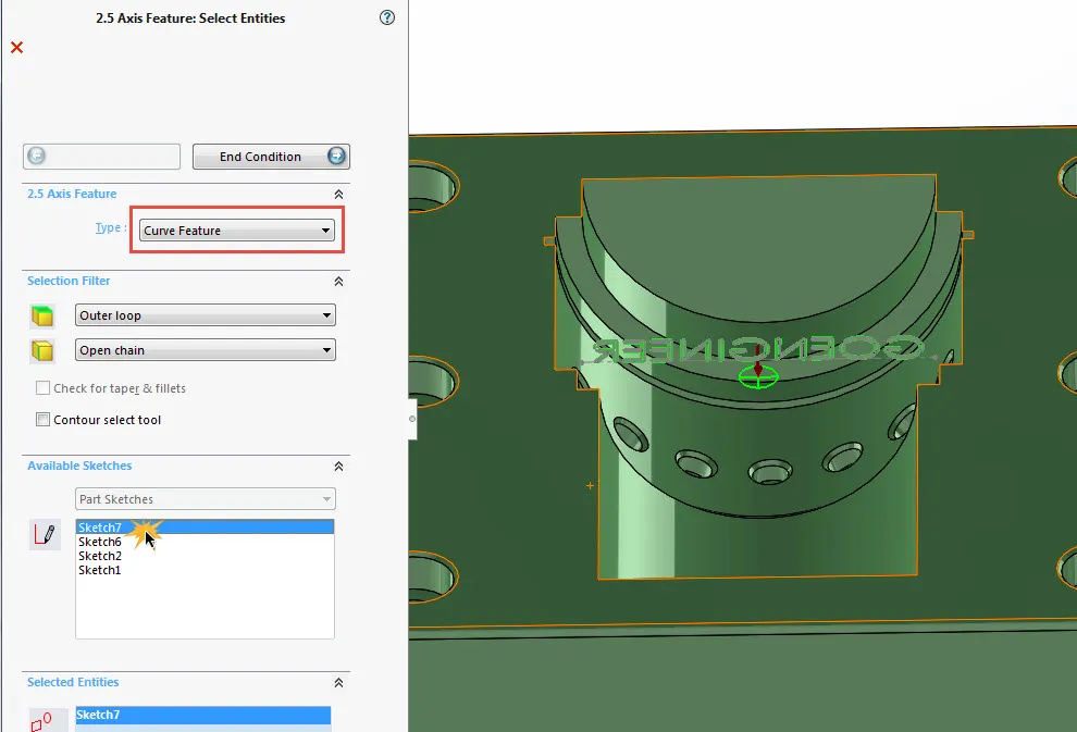
- Curve Feature Selection
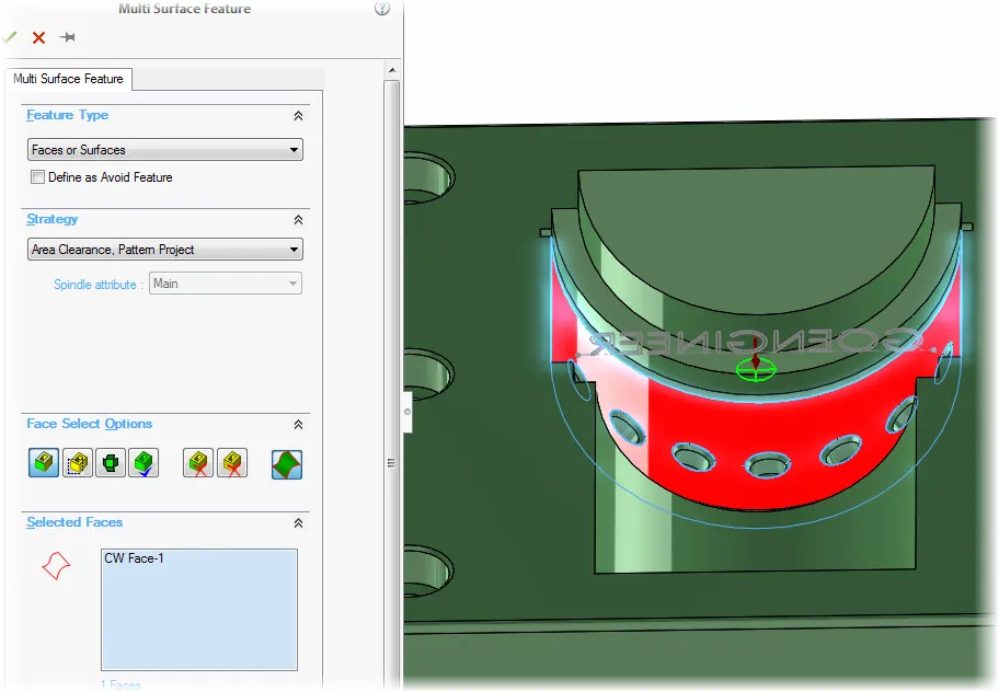
- Add a Multi Surface Feature
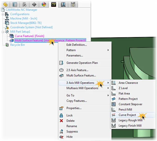
- Create Curve Project Feature
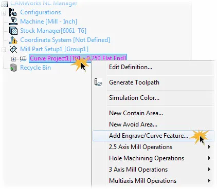
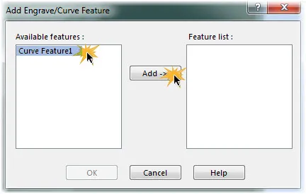
- Add Engrave/Curve Feature
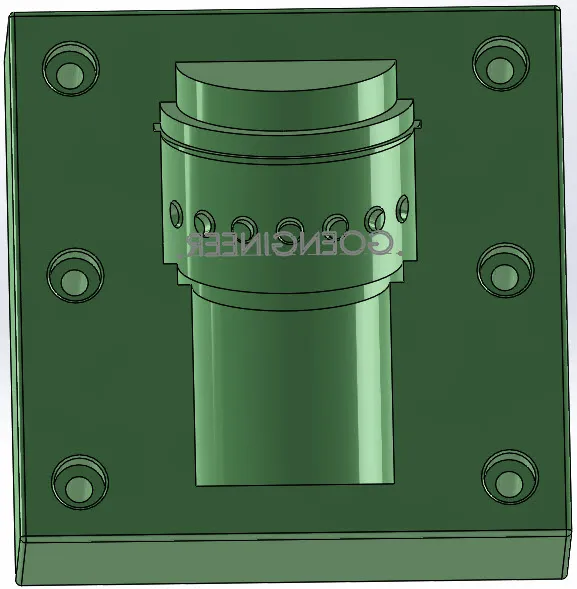
Sketch Annotation
To be able to use the feature, there must be a sketch that it can use. I have a sketched annotation that I want engraved named “GOENGINEER” below in Figure 1.