Being Flexible with the SOLIDWORKS Flex Feature
Over the years, I have encountered engineers who are still creating multiple part files for the same part. Confusing statement? Well, let me explain. Suppose that I have a rubber component, a spring, or even a sheet metal clip, that has two states. These components might have a natural, uncompressed state, which might be how it is manufactured, and then a flexed state for when it gets compressed in an actual assembly. Therefore, one might require two separate part files, one for each state that the component is in. Although this might be a viable option, the SOLIDWORKS Flex feature might offer a time-saving alternative/solution for this type of design requirement.
SOLIDWORKS Flex Feature
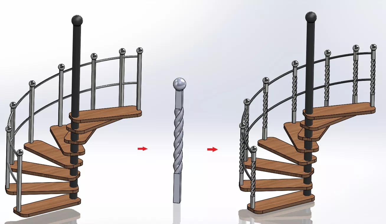
With the SOLIDWORKS Flex feature, you can create some very complex designs without much effort. It can be used for various applications, including concept development, mechanical design, industrial design, stamping dies, molds, and more. The Flex feature can change either a single body or a multibody part, and includes 4 different flex types: Bending, Twisting, Tapering, and Stretching. Consider the baluster component of the spiral staircase below. We can take a simple square design and, with the aid of the Flex feature, create a more aesthetic look.
Flex Feature PropertyManager
The Flex feature PropertyManager starts with the component that you want to bend, twist, taper, or stretch. Then, depending on your selection, there are options for positioning and defining the flex.
In this baluster example, I chose the Twist type, resulting in an option for total twist angle (540°). From there, I can set where I want the twist to begin and end via the positioning of the Trim Planes. Locate them by dragging and dropping the red or green planes themselves, by selecting a reference entity, or by typing in an actual distance value from their default locations (250mm in this example).
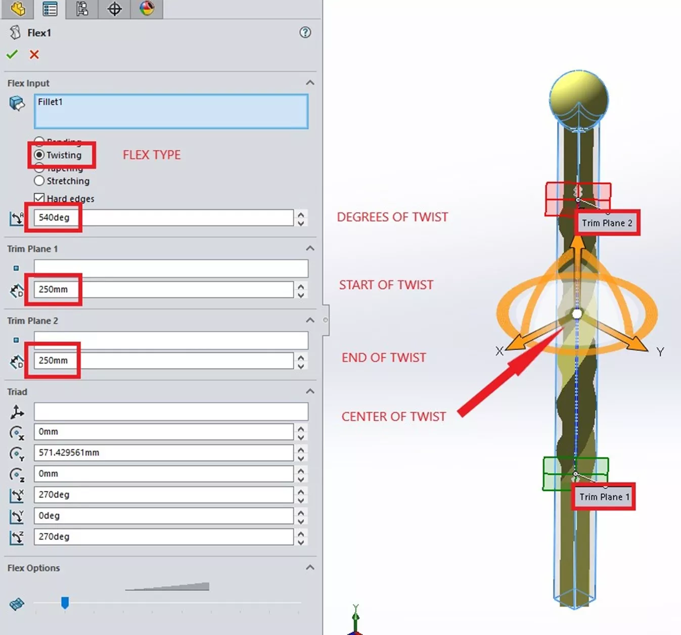
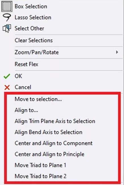
If the Trim Planes need to be repositioned or re-oriented, right-click on the bright white sphere at the center of the big orange triad. In the shortcut menu are options for realigning the Trim Planes and centering and/or moving the triad, as the center of the triad is the center of the Flex.
Flex Feature Design Tip
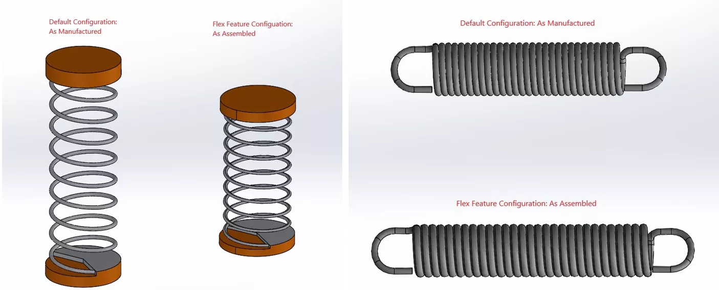
So, how do I avoid having to create two different part files of the same part? By using the Flex feature and configurations. The example images below show a default 'as manufactured' configuration and an 'as assembled' configuration. The Flex feature is suppressed in the default configuration and unsuppressed in the 'as assembled' configuration.
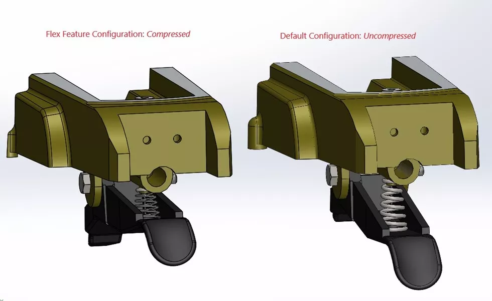
The following example shows how this technique is used in an assembly. Here, I can show the range of the lever component by creating two configurations of the spring. One configuration is the spring in its free state, while the other uses the Flex feature with the spring in its compressed state.
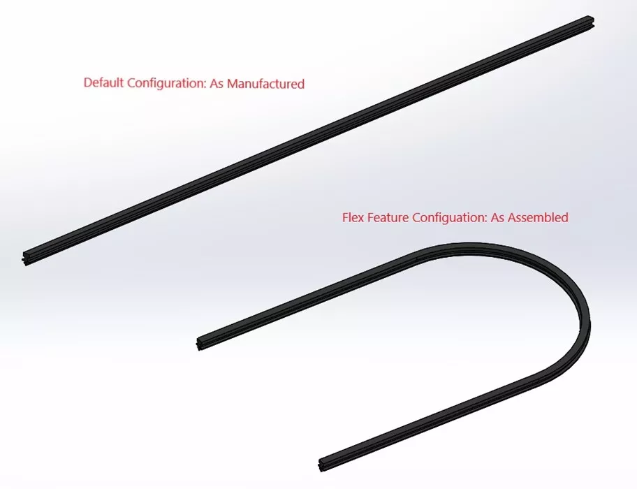
Lastly, we have a rubber component example. In one configuration, the rubber seal is in its manufactured state, whereas in the other configuration, the seal is in its flexed/assembled state.
Conclusion
So, now you have a simple solution for showing flexible components in both states: as manufactured and as assembled. Keep in mind that the SOLIDWORKS Flex feature will cause the geometry to distort, so you probably won’t want to use it for manufacturing purposes and/or drawings.
If you would like to learn more about the Flex feature or if you need help applying it to your component(s), set up an Application Mentoring Session with one of our Certified SOLIDWORK Experts.
Want to learn more? Check out more tutorials below. Additionally, check out the GoEngineer Community, where you can create forum posts, enter design contests, and answer questions from other SOLIDWORKS users.
SOLIDWORKS CAD Cheat Sheet
SHORTCUTS ⋅ MOUSE GESTURES ⋅ HOT KEYS
Our SOLIDWORKS CAD Cheat Sheet, featuring over 90 tips and tricks, will help speed up your process.

Related Articles
Using SOLIDWORKS Sensors to Monitor Surface Area
Why Are My Centerlines Solid in SOLIDWORKS?
AI in SOLIDWORKS: What It Is (and What It Isn’t)
Change Slot Orientation Using SOLIDWORKS Hole Wizard Feature

About Ken LaVictor
Ken LaVictor is a Sr. Application Engineer based out of Pleasant Ridge, MI. He earned his BSME, as well as his Master's of Science degree in Systems Engineering. Since joining the VAR channel in 2004, Ken has earned his Elite AE, SOLIDWORK Expert, and Simulation Expert certifications. In addition to supporting sales, Ken also teaches the SOLIDWORKS and Simulation training courses, assists with technical support, and conducts Application Mentoring Sessions (AMS).
Get our wide array of technical resources delivered right to your inbox.
Unsubscribe at any time.